
1. Both filters are digital filters. The digital filter is divided into a finite impulse response (FIR) filter and an infinite impulse response (IIR) filter depending on the impulse response. For FIR filters, the impulse response decays to zero for a limited time, and its output depends only on the current and past input signal values. For IIR filters, the impulse response should theoretically last indefinitely, and its output depends not only on the current and past input signal values, but also on past signal output values.
2. FIR: finite impulse response filter. Limited description of its impulse response is finite. Compared with IIR, it has the advantage of linear phase and easy design. This also shows that the IIR filter has the disadvantage that the phase is not linear and is not easy to design. On the other hand, IIR has the disadvantage that FIR does not have. It is to design filters with the same parameters. FIR requires more parameters than IIR. This also means that you need to increase the amount of DSP calculations. DSP requires more computing time and has an impact on the real-time performance of the DSP.
The following are the design of the low pass filter.
FIR design:
The design of the FIR filter is relatively simple, that is, to design a digital filter to approximate an ideal low-pass filter. Usually this ideal low pass filter is a rectangular window in the frequency domain. According to the Fourier transform, we can know that this function is a sampling function in the time domain. Usually the expression for this function is:
Sa(n)=sin(n∩)/nâˆ, but this sampling sequence is infinite and the computer cannot calculate it. Therefore, we need to cut off this sampling function. That is to add a window function. It is the legendary window. That is, the time domain sampling sequence is multiplied by a window function, and the infinite time domain sampling sequence is cut into a finite sequence value. However, after windowing, the frequency domain of the sample sequence is also affected: the frequency domain at this time is not an ideal rectangular window, but a low-pass filter with a transition band and a ripple. Generally, depending on the added window function, after the window is sampled, the stopband attenuation of the low-pass filter obtained in the frequency domain is also different. Usually we choose a suitable window function based on this stopband attenuation. Such as rectangular window, Hanning window, Hamming window, BLACKMAN window, Caesar window and so on. After selecting a specific window function, the required order and the expression of this window function are calculated according to the parameters of the designed filter. Then use this window function to multiply the sample sequence to get the impulse response of the actual filter.
IIR design (bilinear transformation method):
The design concept of IIR is as follows: the transfer function of an analog filter is determined according to the parameters of the filter to be designed, and then the design of the digital filter is performed by bilinear transformation or impulse response invariance according to the transfer function. . Its design is more complicated, and the complexity lies in the determination of its analog filter transfer function H(s). This can be done by software. Then, let's talk about its specific implementation steps: First you need to determine what kind of filter you need, Butterworth type, Chebyshev type, or any other type of filter. When you select a model, you can determine the order and transfer function expression based on the design parameters and the calculation formula for this filter. Usually there is a problem of pre-distortion in this process (this is only a problem that needs to be paid attention to by the bilinear transformation method, and the impulse response invariant method does not have such a problem). After determining H(S), the difference equation of its digital domain can be obtained by bilinear transformation.
3. Comparison of IIR and FIR is discussed in some books. I quote Chen Huaiyu's "Digital Signal Processing Tutorial - MATLAB Interpretation and Implementation":
In terms of performance, the IIR filter transfer function includes two adjustment factors of zero point and pole, and the only limit to the pole is within the unit circle. Therefore, high selectivity can be obtained with a lower order, using less memory cells, less computation, and higher efficiency. But this high efficiency comes at the expense of phase nonlinearity. The better the selectivity, the more severe the phase nonlinearity. The pole of the FIR filter transfer function is fixed at the origin and is immovable. It can only change its performance by changing the position of the zero. Therefore, in order to achieve high selectivity, a higher order must be used; for the same filter design index, the order required by the FIR filter may be 5-10 times higher than the IIR filter. As a result, the cost is higher, and the signal is higher. The delay is also large; if the linear phase is required, the IIR filter must be added to the all-pass network for phase correction, which also greatly increases the order and complexity of the filter. The FIR filter can get a strict linear phase.
Structurally, the IIR filter must use a recursive structure to configure the poles and ensure that the poles are in the unit circle. Due to the finite word length effect, the coefficients are rounded during the operation, causing a pole offset. This situation sometimes causes stability problems and even parasitic oscillations. On the contrary, as long as the FIR filter adopts a non-recursive structure, there is no stability problem in both theoretical and practical finite precision operations, and thus the frequency characteristic error is also small. In addition, the FIR filter can use the fast Fourier transform algorithm, and the operation speed can be much faster under the same order.
In addition, it should be noted that although the design of the IIR filter is simple, it is mainly used to design filters with segmentation constant characteristics, such as low-pass, high-pass, band-pass and band-stop, which often cannot be separated from the analog filter. . The FIR filter is much more flexible, especially because it is easy to adapt to certain special applications, such as the digital differentiator or the Hiller converter, so it has greater adaptability and a wide range of applications.
From the above simple comparison, we can see that the IIR and FIR filters have their own strengths, so in practical applications, we should choose from many aspects. From the point of view of the use requirements, in the case of insensitivity to phase requirements, such as language communication, it is more appropriate to use IIR, so that it can fully utilize its economical and efficient features; for image signal processing, data transmission and other systems that carry information by waveform, Then the linear phase is required to be higher. If possible, it is better to use a FIR filter. Of course, more factors may be considered in practical applications.
Regardless of IIR and FIR, the higher the order, the larger the signal delay. At the same time, in the IIR filter, the higher the order, the higher the accuracy requirement of the coefficient, otherwise it is easy to cause the error of the finite word length to move the pole to the unit outside the park. . Therefore, it is considered comprehensively in order selection.
IIR filter (Chebyshev filter) comparison of each filter (IIR and FIR, digital and analog) Chapters 19, 20, 21, mainly on the comparison of IIR filters and filters
IIR filtering does not use convolution operations, but uses recursive operations, so execution speed is fast, but performance is not necessarily better than FIR filtering. The impulse response of the IIR consists of an attenuation index signal.
The recursion relation of IIR input and output is:
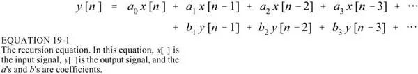
The relationship between the IIR recursive coefficient and its frequency response can be converted by a Z transform, which is not involved here.
Different filtering can be achieved by taking different recursive coefficients (a and b in the figure below):
Of course, this is the simplest application. There are certain exquisite formulas and formulas for recursive coefficients. It is omitted here.
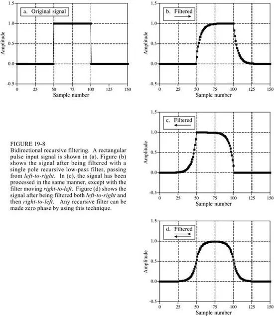
FIR can be linear phase, that is, the impulse response is bilaterally symmetric, and the IIR is usually nonlinear phase. This is because the FIR determines its time domain waveform and frequency response at the time of design, and the IIR determines the recursive coefficients in the design and does not determine what the waveform looks like.
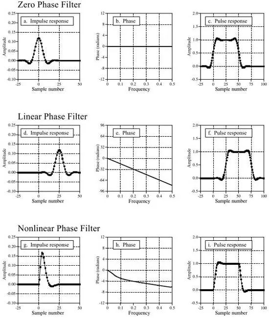
In order to make the IIR achieve linear phase, two-way operation can be performed, as shown in the following figure:
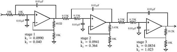
Chebyshev filter
Chebyshev filtering is applied in the frequency domain, and performance is certainly not comparable to sinc window function filtering, but it is very fast.
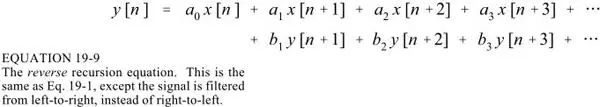
The Chebyshev response is a mathematical strategy for achieving a faster roll-off by allowing ripple in the frequency response. As the ripple increases (bad), the roll-off becomes sharper (good).
Understanding of the pole:
The more poles, the better the performance.
The coefficients of the filter can be determined by looking up the table.
Comparison of various filters
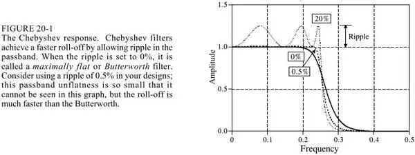
1. Analog vs number
If the signal needs to be filtered, is it filtered during the simulation phase? Still filtering after digitization?
The comparison below shows that digital filtering has the performance that is difficult to achieve with analog filtering, but the speed is slow, and the amplitude of the analog filtering and the dynamic range of the frequency are larger.
The implementation of analog filtering in this example:
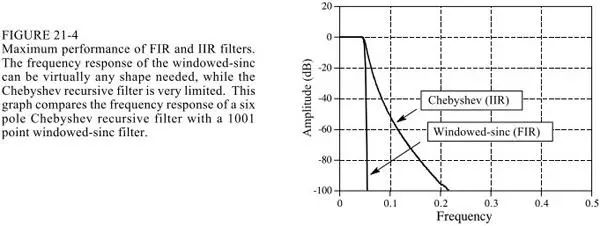
2.sinc window function vs Chebyshev
The following picture is compared
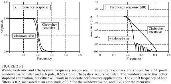
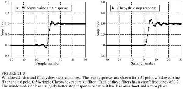
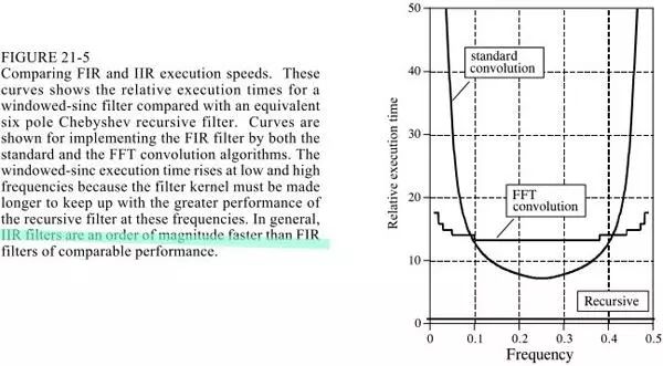
The sinc window function is computed using convolution, and Chebyshev uses a recursive equation. Of course, convolution can be done with fft convolution, that is, DFT and then frequency domain four operations and then DFT inverse transform, which can improve the speed, but there is still no recursive equation fast. On the other hand, the filtering performance of the sinc window function can be done very well.
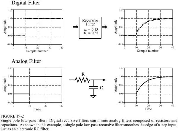
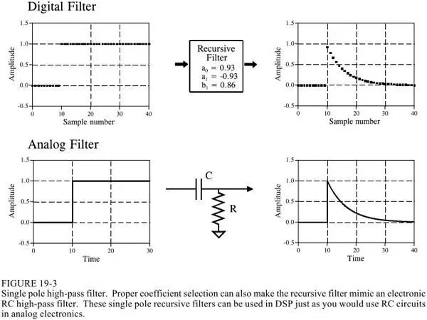
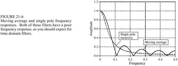
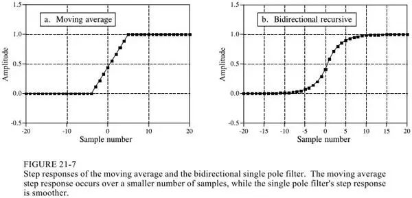
3. Moving average vs single pole
Reverse Conducting Thyristor(RCT)
Reverse Conducting Thyristor(RCT) is also called Reverse- appreciation Thyristor.The characteristic is that a diode is connected in reverse parallel between the anode and cathode of thyristor, so that the transmitting junction of anode and cathode is short-circuited.As a result of this special circuit structure, it has high voltage resistance, high temperature resistance, short turn-off time, low switching voltage and other good performance.For example, the turn-off time of the reverse thyristor is only a few microseconds, and the working frequency is dozens of KHZ, which is better than the fast thyristor (FSCR).This device is suitable for switching power supply and UPS uninterrupted power supply. One RCT can replace one thyristor and one continuous current diode respectively.
Reverse Conducting Thyristor,Original Reverse Conducting Thyristor,New Reverse Conducting Thyristor,Reverse-Conducting Thyristor 2200V
YANGZHOU POSITIONING TECH CO., LTD. , https://www.yzpst.com