In the microcomputer system composed of single-chip microcomputer, the operation of the single-chip microcomputer is often disturbed by the external electromagnetic field, causing the program to run away, and it is in an infinite loop, the normal operation of the program is interrupted, and the system controlled by the single-chip microcomputer cannot continue to work. Will cause the whole system to stagnate and have unpredictable consequences. Therefore, due to the real-time monitoring of the operating state of the single-chip microcomputer, a chip specially used to monitor the running status of the single-chip program is generated, commonly known as the “watchdogâ€. "(watchdog)
Its function is to enable the MCU to achieve continuous operation in an unmanned state. The working principle is: the watchdog chip is connected to an I/O pin of the MCU, and the I/O pin is controlled by the program to periodically go to the gate. The dog is sent to a high level (or low level) on this pin. This program statement is scattered in the middle of other control statements of the MCU. Once the MCU is run due to interference, it enters a certain program segment. In the endless loop state, the program that writes the watchdog pin cannot be executed. At this time, the watchdog circuit will not be able to receive the signal from the microcontroller, and it will be on the pin connected to the reset pin of the microcontroller. A reset signal is sent to reset the microcontroller, that is, the program starts from the beginning of the program memory, thus realizing the automatic reset of the microcontroller.
The role of the microcontroller watchdog circuitThe role of the watchdog: The watchdog timer is a counter. The basic function is to restart the system after a software problem occurs and the program runs away. The watchdog counter automatically counts when it is working normally. The program flow periodically resets it to zero. If the system is stuck or running somewhere, the timer will overflow and will enter the interrupt. Perform some reset operations in the timer interrupt to restore the system to normal working state, that is, during the normal operation of the program, reset the watchdog as scheduled to ensure the selected
The timed overflow is zeroed and the processor is restarted. Software reliability has always been a key issue. Anyone who uses the software may experience a computer crash or a runaway problem, which is also true in embedded systems. Due to the limited anti-interference ability of the single-chip microcomputer, in the instrumentation of the industrial field, it often causes a crash due to voltage instability and arc interference. In the case of unattended water meters, electricity meters, etc., it is also impossible to restart due to system interference. In order to ensure that the system automatically returns to normal after interference, the use of the Watchdog TImer is very valuable.
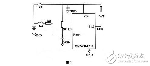
Some of the popular MCUs on the market today are embedded with internal WDTs such as TI's MSP430 series, Philips' P87XXX and P89XXX series, Microchip's PIC column, Atmel's AT89SXX series and Holtek's Htxxx series. However, there are some errors in these internal watchdogs at work. Some engineers in the design process, because of this, caused the system to be abnormal. MSP430 series MCU is a new generation of MCU developed by Texas Instruments (TI) in recent years. This series is a 16-bit, new concept hybrid MCU with a reduced instruction set and ultra-low power consumption. Among the many MCU series, it has become a dazzling star because of its low power consumption, rich on-chip peripherals and convenient and flexible development tools. It has its own watchdog and reset circuit. In theory, if the program runs away, it can be reset by the watchdog. However, in the actual use process, it was found that the role of the watchdog is not foolproof. The following experiment proves this. The experimental circuit is shown in Figure 1.
List of test procedures:
#include"msp430x12.h"
Void main(void){
P1dir l=0x0f; //Set p1.2-.p1.0 as output
For(;;){
volaTIle unsigned int i;
Wdtctl=wdtpw+wdtcncl;
/ / Reset wdt
Piout==0x0t;
i=5000;
Do(i--)
While(i!=0);
}}
After the above experiment is started, if the program is running normally, the LED will flash. By default, the watchdog of the MSP430 is allowed, and the running program continuously accesses the watchdog. In theory, this system will not fail to start, because even if the startup fails, the watchdog should start within hundreds of milliseconds to reset the entire system. Based on this idea, the reset of the microcontroller is tested. K2 is disconnected and is continuously generated with K1. Reset signal, test the success rate of the watchdog to restart the system. When K2 is closed, the reset terminal is high. In theory, K1 cannot effectively generate a reset pulse to observe whether the watchdog is active.
Experimental results and analysis
The experimental results are as follows: K2 disconnected, continuous switch K1, power-on restart system, average 155 failures 1 time (LED does not flash), that is, watchdog failure probability 0.6%; K2 closed, continuous switch K1, average 18 times Failure 1 time (LED does not flash), and once failed, will continue to fail, the watchdog inefficiency accounted for about 5.5%. In addition, when other series of single-chip microcomputers with the built-in watchdog are used instead of the MSP430 in the experiment, the experimental results are still the same when the program block is modified accordingly. This shows that the problem faced by the single-chip microcomputer with built-in watchdog is the same. After analysis, there may be the following reasons:
1 Since the watchdog's clock is not independent, the count clock and the system are on the same crossover link, so the watchdog cannot operate effectively when there is a problem in the system.
2 Since the clock can be set by software, when the startup fails, the power-on clock may be in the neutral state, and no clock watchdog cannot take effect.
3 Some watchdogs need to be set or started by software. Therefore, after the startup fails, the initialization program is not activated, and the CPU may jump to the random code to disable the watchdog. Such a watchdog needs to have a reliable power-on reset as a guarantee. Therefore, in theory, the original design is unreasonable. Based on the above analysis, the off-chip watchdog dedicated chip TPS3823 is used to provide counting pulses by an independent frequency division oscillating circuit. The experimental circuit is shown in Figure 2.
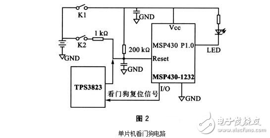
In the above circuit, the TPS3823 outputs a timing overflow signal to the Reset terminal. In the block, the CPU should continuously output the dog feed signal through the I/O port to clear the watchdog counter. In this circuit, the same action of K1 and K2 in the above test is repeated, and the system restart success rate reaches 100%.
Future built-in watchdogs must have independent and reliable clocks. After the system is powered up, the watchdog is enabled and requires no software settings. It can only be disabled by external hardware jumpers or internal fuses. At present, external watchdogs must be considered if high-reliability embedded systems are required. Another problem with the built-in watchdog is that after a system reset, the program should determine whether the reset is normally powered-on or the program is running away from the watchdog, thereby determining whether the field data should be retained. This is also a consideration in watchdog applications.
Watchdog system design skillsExternal watchdogs are an important and critical tool in the embedded system engineer's toolbox. However, in order to catch faults and prevent malfunctions, the dogs must be properly designed. Therefore, the following five tips should be considered when designing a watchdog system.
Tip 1 - Monitor your heartbeat
The simplest function an external watchdog must have is to monitor a periodic "Heartbeat" signal generated by the main application processor and to send an error signal when the heartbeat is abnormal. Heartbeat monitoring can be used for two different purposes: First, after passing a functional check that has been performed in software, the microcontroller (MCU) should only generate heartbeats to ensure that the software is working properly. Second, if the real-time response of the system has been compromised, the heartbeat should be able to show up.
Monitor heartbeat for software features and real-time response, through an easy-to-use, "dumb" external watchdog. The external watchdog should have a heartbeat cycle that is assigned along the ability of a heartbeat window to appear. The heartbeat window allows the watchdog to detect when the system's real-time response is compromised. In the event that the feature or real-time check fails, the watchdog will attempt to recover the system through a reset of the application processor.
Tip 2 - Using a low-performance MCU
A simple timer-based external watchdog monitors heartbeats at relatively low cost, but this severely limits the ability of the watchdog system and the likelihood of recovery. In fact, a low-performance microcontroller can be used as an external watchdog timer, so why not add some intelligence to the watchdog and use a microcontroller? Microprocessor firmware (Firmware) can be developed to meet the needs of a heartbeat monitoring window that adds many features.
A "smart" watchdog is sometimes referred to as a supervisor or a safety watchdog and has been used for many years in different industries, such as the automotive sector; in addition, microcontroller-based watchdogs are often used primarily For safety critical applications. Currently development tools are quite available and hardware costs are low, such designs are cost effective and so are they in other applications.
Tip 3 - Supervise key system functions
Using a small microcontroller as a watchdog decision opens up the infinite possibilities of how the watchdog should be used. The first role that can be given to a smart watchdog is usually the important system functions that are supervised, such as system current or sensor status. An example of how a watchdog can monitor current is to take an independent measurement of current and provide a monitored value to the application processor, after which the application processor can compare the value read by the watchdog with itself. If there is a disagreement between the two, the system will execute the FaultTree, which is considered appropriate by the application.
Tip 4 - Observe a channel
Sometimes an embedded system can be like a watchdog and the application processor can work as expected, but the external inspector is in a non-responsive state. In such a state, it is feasible to bind a smart watchdog to a channel such as a Universal Asynchronous Receiver Transmitter (UART). When the watchdog is connected to the channel, it not only monitors channel traffic, but also receives specific commands for the watchdog.
A good example of this is the watchdog designed for small satellites, which monitors the radio communication between the aircraft computer and the ground base station. If the aircraft computer becomes unresponsive to the radio, the watchdog will receive a command and then execute and reset the aircraft computer.
Tip 5 - Consider the external timing reset function
Using a microcontroller to execute the watchdog has additional features that increase its complexity and a new software unit-to-system design. Therefore, the problem of the watchdog in the system is undoubtedly monitored by the engineer's mind. How will the watchdog recover if the watchdog “self-enlarges the fake�
One option is to use the dumb external watchdog timer discussed earlier. A smart watchdog will have a dumb watchdog timer that generates a heartbeat from a reset condition; another option is to make the application processor behave like a watchdog. Care must be taken here to give the best way to ensure that both processors remain as expected.
Simple design ensures the feasibility of the watchdog
The purpose of the intelligent watchdog is to monitor the system and the main microcontroller to ensure they operate as expected. In system design, the watchdog allows for the very versatility it supports. Developers need to keep in mind the possibility of increasing the complexity of the smart watchdog, and the watchdog itself must contain potential failure modes and errors. More importantly, the design of the watchdog should be simple and minimally necessary to ensure that it can be thoroughly tested and verified.
Watchdog technology and its anti-jamming measuresWith the continuous improvement of industrial automation level, the single-chip application system composed of MCS-51 single-chip microcomputer has been widely used, such as cement raw material batching system, electronic belt scale feeding control, various on-site intelligent measuring instruments. However, the working site conditions are harsh, the interference is large and the amplitude is large, which seriously affects the normal operation and reliability of the application system, and even causes the application system computer to enter an infinite loop, which is often called the program "running." The computer reliability problem caused by this has always been an important topic for people to study.
Shielding, filtering, decoupling, isolation, grounding and other measures can effectively improve the anti-jamming capability of the system, but it is difficult to eliminate the crash caused by the program "running away" when strong interference occurs. The "watchdog" technology can self-diagnose and resume the system when the program "runs away", which is a powerful weapon for the anti-interference of the single-chip application system. Of course, it is conditional on the rationality and maturity of the system's hardware and software design and development, otherwise it will cover up the human defects and deficiencies in the system design and development process.
"Watchdog" technology and its suppression of interference1, the program "running" attack on the system
(1) The value of the program counter PC is attacked and becomes a random piece of data.
(2) The control words and flag parameters set by the system may be attacked after being “runningâ€.
(3) The data memory RAM content is attacked and the like.
2, "watchdog" technology
"Watchdog" is derived from "Watch dog, Watch dog timer", or timing monitoring technology, which is essentially a resettable timer. The principle is shown in Figure 1 and 2.
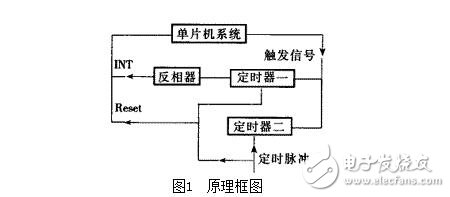
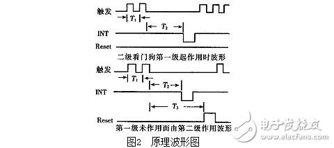
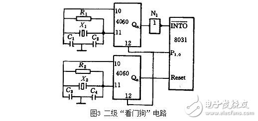
When the program is running normally, the computer sends a pulse trigger timer to the timer by cycle T1 (or initializes the timer by software with T1), and the timer operation time controlled by the timing pulse is T2 (T3). When T1 < T2 (T3), the timer does not operate and is in a sleep state. When the computer is damaged by strong interference, the content of the program counter PC is no longer the correct code of the program, but may be a random piece of data, which will make the instruction incorrect, which will inevitably lead to chaotic "running" of the program. Enter the endless loop and crash. Conversely, because the program leaves the normal cycle, the timer trigger pulse is also lost. After the T2 (T3) time, the "watchdog" timer is activated, and a reset signal is sent to the CPU to reset it, which will "run away". The program starts from PC=0000H and is included in the normal track. However, some production processes cannot be started from scratch. The application is a loop body, and there are initialization programs at the beginning, including various registers, pointers, variables, control words, and so on. At this time, the state cannot reflect the state of "running", and sometimes there are safety risks in terms of human body and equipment. In this case, after the program "runs away", you should try to find the breakpoint when the error occurs, and you can use the secondary "watchdog" method. The timer is set to the highest level of the timer, and the interrupt request signal is issued first. The CPU responds to the interrupt and turns to the interrupt handler to restore the system. The second stage "watchdog" circuit only starts the Reset signal after T3 when the first stage is inactive.
3. Implementation method of "watchdog" technology
(1) In the system configuration, select the microcontroller with the "watchdog" circuit in the chip, such as the 89C52 of ATMEL.
(2) Optional special "watchdog" circuits, such as the X25043/45 from Xicor, USA, and the MAX813L from MAXIM, all of which can form separate "watchdog" circuits.
(3) It is composed of a counter, a one-shot, a timer, and the like. In Figure 3, a secondary "watchdog" circuit is constructed using 4060.
Since the /I/N/T/O interrupt entry 0003H only has the 0003H~000AH unit available for the interrupt service routine, it is likely to be unable to accommodate the interrupt service routine, so a JMP Watch dog command should be arranged in it. Due to "running", the PC value has been corrupted before responding to the interrupt. After the response is interrupted, the content is automatically pushed onto the stack. Therefore, two POP A instructions must be used to pop the useless content, so that the interrupt is returned by the stack. Giving PCs the correct value of "running" is especially important when designing interrupt service routines. The trigger pulse to the 4060 is restored by inverting P1.0. In the interrupt service, the diagnosis, repair, and finding the correct entry of the address at the "running" should be arranged and pushed onto the stack before returning. When RETI is executed, the breakpoint address entry of the "running" is automatically popped to the PC and resumes normal operation. Where is the P1.0 inversion instruction inserted? The interval between the two CLR P1.0 instructions should be less than the timer timing T1 < T2 by the calculation instruction cycle, and T2 = (1.5 ~ 2) T1 can be taken.
(4) Using the 8031 ​​on-chip timer/counter 8031, there are two 16-bit timer/counters on the chip, and the timer T0 is available. When the application initializes T0, its timing time T2 is set longer than the application loop body execution time T1, and it is preferable that T2 = (1.5 to 2) T1. When the program is normal, T0 will not overflow, and it will overflow when “runningâ€. The timer/counter control register TCON TF0 (TCON.5) is set by the 8031 ​​internal hardware TF0=1, and an interrupt signal is issued. Let the 8031 ​​adopt 12MHz crystal oscillator, and get the 1MHz timing clock after the timer is internally divided by 12, corresponding to the timing time of 1μs, the maximum time can be about 65.5ms. If the application cycle time T1=10ms, then T2=2T1=20ms can be taken. The initial value X of the timer can be determined by:
(216-X)×1μs=20ms
X=45536D=B1EOH
Timer initialization procedure:
MOV TLO, #OEOH
MOV THO, #OB1H; timer/counter T0 is written to the initial value
MOV TMOD, #O1H; Set the timer/counter mode of operation 1
SETB TRO; start timer / counter T0
Use the following command to set the T0 priority during system initialization of the application:
SETB EA; open interrupt
SETB ETO; Allow T0 interrupt
SETB PTO; set T0 interrupt priority
Compared with the /I/N/T/O interrupt service flow (see Figure 4), the T0 interrupt service flow has an interrupt entry of 000BH, and the P1.0 inverted instruction is removed. The rest are the same. Regain control of the control with the highest priority interrupt and return the system to normal.
6
4, breakpoint search and recovery
The search and recovery of breakpoints is the most concerned issue. Our method is to extend an external data memory to store the value of the PC before the "runaway" breakpoint (or near the breakpoint) and some important variables and pointers. And the value of the control word. The trigger pulse sent to the "watchdog" during normal operation is reversed, delayed, etc. as a chip select signal of the external extended RAM, and the content in the external RAM is refreshed at a timing of T1. When "running", the external RAM is prevented from being attacked due to the loss of the trigger pulse, and the reliability of the content is guaranteed. As T1 decreases, the recovered value gets closer to the breakpoint value, but it is worth investigating to find the breakpoint very accurately. The breakpoint value can be read out because the output trigger pulse is restored by P1.0 during the interrupt response.
Conclusion
The "watchdog" is a powerful means of dealing with "running", and the "watchdog" technology has a considerable role in the production process due to specific production conditions. We used a secondary "watchdog" technology in the technical transformation of a cement plant's batching system. The system has withstood the test of various strong disturbances for more than two years and achieved satisfactory results.
For the diagnosis and recovery after "running", especially how to find the program "running" breakpoint more accurately, and recovering the damaged data, although there are many softwares available, it is worthy of more attention.
Biomass Gas Generator,Biomass Electricity Generator,Gas Powered Electric Generator,Gas Generator
Jiangsu Vantek Power Machinery Co., Ltd , https://www.vantekpower.com
