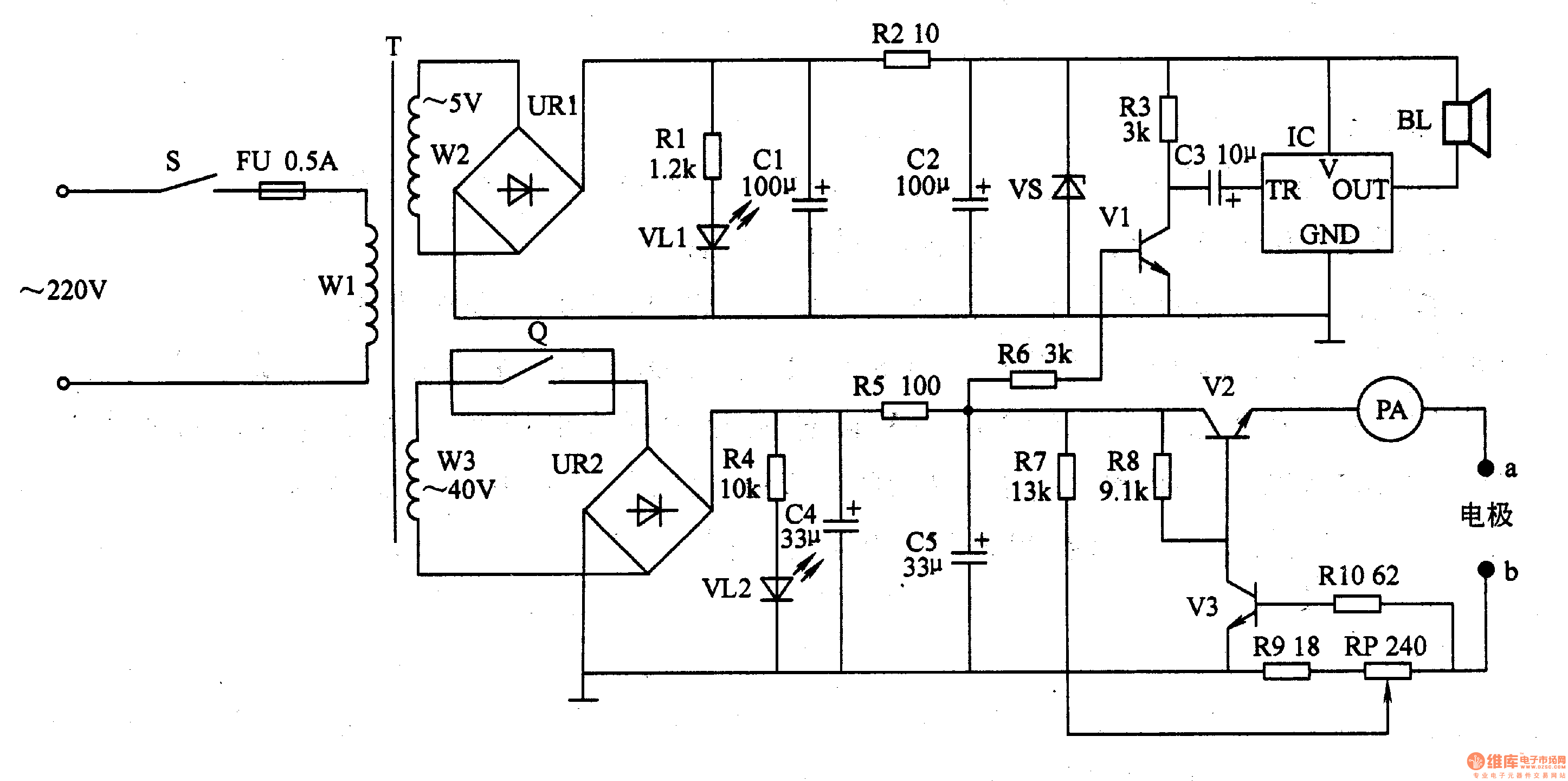
Circuit Operation Principle The bone hyperplasia therapy instrument circuit consists of a power supply circuit, a constant current output circuit, and an audible alarm circuit, as shown in Figure 9-23.

The power circuit consists of power switch S, fuse FU, power transformer T, timer Q, rectifier bridge stack UR1, UR2, current limiting resistor Rl, R2, R4, R5, LED VLl, VL2, filter capacitor Cl, C2 C4, C5 and Zener diode VS.
The constant current output circuit is composed of resistors R7-R10, potentiometer RP, transistors V2, V3, ammeter PA, and electrodes a, b.
The sound alarm circuit is composed of resistors R3, R6, a capacitor C3, a transistor V1, a music integrated circuit IC, and a speaker BL.
After the power switch S is turned on, the AC 220V voltage is stepped down by T, and an AC 5V voltage and an AC 40V voltage are respectively generated on the W2 winding and the W3 winding of the T.
The AC 5V voltage is divided into two channels after being rectified by URl: one is GL1 after being depressurized by Rl current limiting; the other is filtered by Cl, C2, R2 and VS to provide 3V DC working voltage for the alarm circuit.
After the timer is turned on, the AC 40V voltage is rectified by UR2, and the VL2 is lit after one step is stepped down by R4, and the other channel is filtered by C4, R5, C5 and added to the constant current output circuit. The voltage across C5 is also applied to the base of V1 via R6, so that V1 is saturated and the lC and BL are not working.
The voltage at both ends of C5 is adjusted by constant currents such as V2, V3, R7-RlO and RP, and then added to the bone hyperplasia site of the human body through electrodes a and b. Adjusting the resistance of RP can change the output current (the patient can adjust according to the actual bearing capacity, the maximum output current is 3OmA).
At the end of the timing time, the internal control contacts of the timer are turned off, so that VU is extinguished, the voltage across C5 gradually disappears, the constant current output circuit stops working, and Vl is turned off, the IC triggers the work, and BI" sounds a music alarm, notifying The treatment time for medical staff has ended.
Component selection
Rl, R3, R4, R6 and R8-RlO all use 1/4W metal film resistors; R2, R5 and R7 select 1/2W metal film resistors.
The RP uses a small synthetic carbon film potentiometer or a multi-turn potentiometer.
Cl-C3 selects aluminum electrolytic capacitors with a withstand voltage of lOV; aluminum and electrolytic capacitors with a withstand voltage of lOOV are selected for both C5 and C5.
VS selects 1/2W, 3V silicon Zener diode.
Both VLl and VL2 use high-brightness light-emitting diodes of φ3mm.
URl selects the rectifier bridge stack of lA, 5OV; UR2 selects 0.5A, lOOV rectifier bridge stack.
Vl selects S9013 or 3DG6 type silicon NPN transistor; V2 selects DDOlB type silicon NPN transistor; V3 selects 3DA87 type silicon NPN transistor.
The IC uses a common music integrated circuit, such as the KDg300 series.
The timer uses a mechanical timer of 0-3Omin.
PA selects 0-3OmA ammeter, such as WXCg and other models.
BL uses 0.25W, 8n miniature electric speakers.
S selects 5A, 220V single pole power switch.
T uses a small power transformer of 1-3W.
The electrodes a and b are made of thin copper plate
Fiber Optic Box,Fiber Optics Box,Fiber Optic Boxes,Fiber Optic Junction Box
Cixi Dani Plastic Products Co.,Ltd , https://www.danifiberoptic.com
