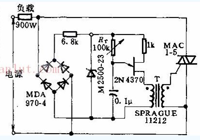
Generally speaking, a full-wave rectification circuit is a circuit capable of converting an alternating current into a single-direction current. At least two rectifiers are combined, one is responsible for the positive direction and the other is responsible for the negative direction. The most typical full-wave rectification circuit is composed of four. A rectifier bridge composed of diodes, generally used for rectification of power supplies. It can also be built by MOS tube. Full-wave rectification circuit: a full-wave rectification circuit having first and second power supply terminals, wherein first and second power supply terminals are respectively provided with first and second power supply potentials, and the first power supply potential is higher than the second power supply potential The full-wave rectifying circuit includes: a differential amplifier having first and second amplifier inputs with an input AC signal interposed therebetween for differentially amplifying an input AC signal, the differential amplifier having a first sum a second amplifier output for respectively generating first and second amplified output voltages, which are inverted from each other; and a voltage reference circuit for generating a reference voltage between the first and second power supply potentials.
This circuit consists of a single junction transistor triggering a triac and a bridge rectifier. Use RT to provide a wide range of control over resistive loads. The pulse transformer T isolates the triac gate from the steady state current of the single junction transistor.

Media Converter And Optical Fiber Switch
Media Converter Optical Fiber Switch fiber optic switcher
Media Converter,Optical Fiber Switch,Fiber Optic Switcher
Chinasky Electronics Co., Ltd. , https://www.chinacctvproducts.com
