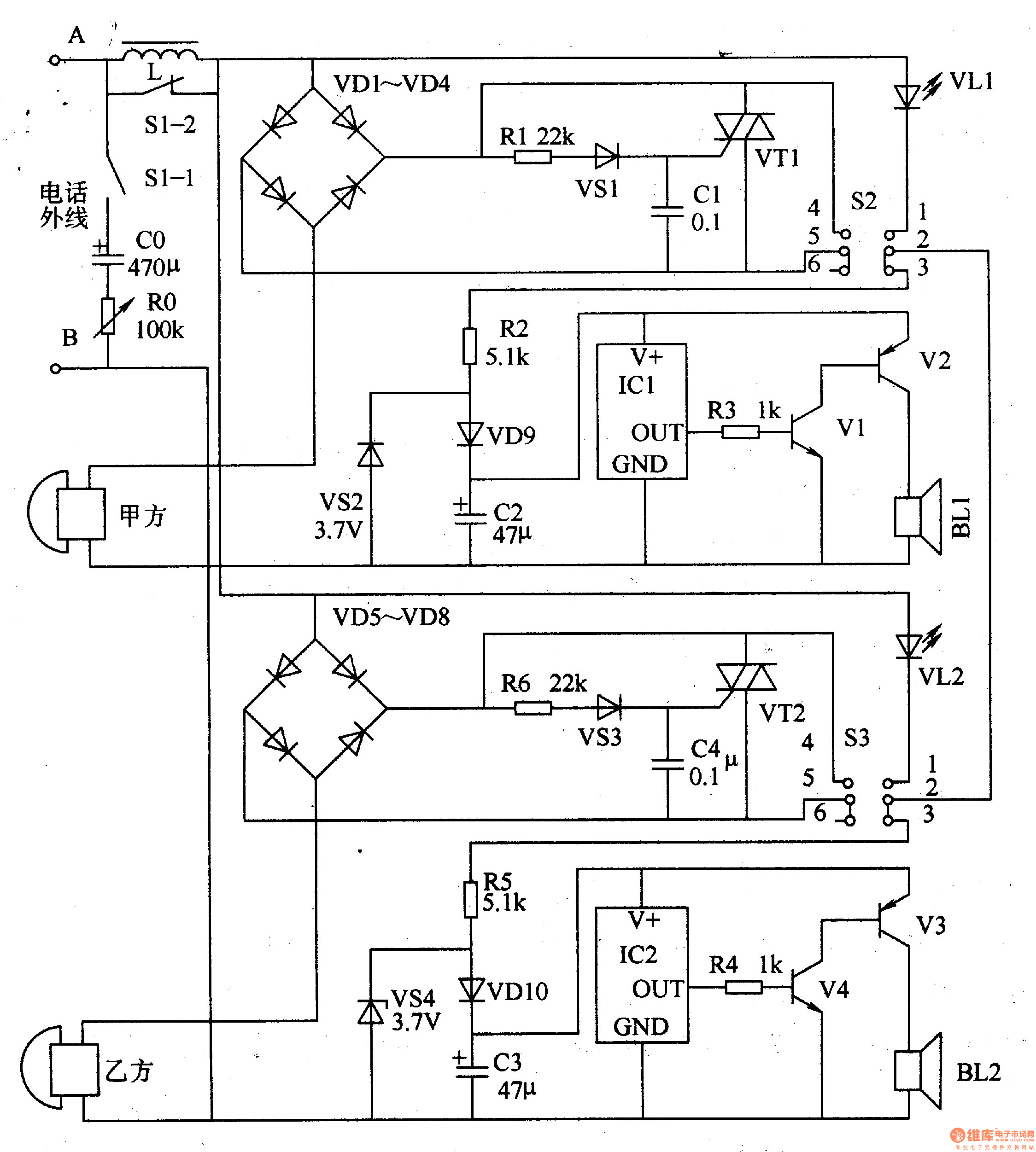
Circuit Operation Principle The telephone line-of-line pager circuit consists of a filter circuit, a two-way calling circuit and a call circuit, as shown in Figure 3-151.

The two-way calling circuit is composed of an integrated circuit ICl, IC2, a resistor R2-R5, a diode VD9, a VD10, a Zener diode VS2, a VS4, a capacitor C2, a C3, a transistor Vl-V4, and a speaker BL1, BU.
The call circuit is composed of transistors VT1, Vn, diodes VDl-VD8, Zener diodes VS1, VS3, resistors R1, R6, capacitors Cl, C4, light-emitting diodes VLl, V, and switches S2, S3.
The filter circuit is composed of a switch S1 (S1-1, S1-2), a capacitor CO, a resistor R0, and an inductor L.
When both the telephone of Party A and the telephone of Party B are on-hook, the voltage on the external line of the telephone is about 48V. At this time, since the DC path cannot be formed, the thyristors VT1 and VT2 are both in the off state.
When there is a telephone call on the outside line (C Party), the ringing signal voltage of about 75V is rectified by VDl-VD4 and VD5-VD8, so that VSl and VS3 are turned on and turned on, and VTl and VT2 are triggered and turned on. Both the machine and the B-party phone ringing.
If Party A picks up the phone first, then Party A's telephone and the call circuit form a DC path, which can be used to talk with the outside line. After the A-side telephone picks up the phone, the voltage on the external line will drop to 8-1OV, and VS3 and VT2 will be cut off. At this time, even if the party picks up the phone, it cannot talk to the outside line.
If Party A wants to transfer this call to Party B, it should press 52 to disconnect the two sets of normally closed contacts (2, 3, 5, 6) of 52, two sets of normally open contacts (1) The 2nd, 4th and 5th ends are connected, so that the calling circuit of Party B is energized, and IC2 outputs music or sound effect signals. After this signal is amplified by V3 and V4, it drives B to emit a beautiful music sound or "beep" sound. VLl glows.
After Party B hears Party A's call, it presses S3 to answer, so that the S3's constant penalty contact is disconnected, the normally open contact is turned on, VT2 is short-circuited, and VL2 is lit. At this time, the B-party telephone can be realized after off-hook. A, B, C calls. If Party A wants to exit the call, it can reset 52 (normally closed contact is closed, normally open contact is disconnected) and then hang up. After S2 reset, VLl goes out.
After Party A hangs up, Party B can also call Party A online and transfer the call to Party A.
When Party A and Party B are in a call, S1 should be pressed to make S1-2 disconnect, S1-1 is turned on, and the filter circuit works, which can eliminate the dial tone, busy tone and other interferences sent by the program-controlled switch, and can also reduce the call. The side tone of the time improves the quality of the call.
Component selection
RO selects 1/2W organic solid variable resistor for use; Rl-R6 selects 1/4W carbon membrane resistor or metal membrane resistor for use.
C0, C2 and C3 are all made of aluminum electrolytic tantalum containers with a withstand voltage of 16V; Cl and C4 are made of monolithic capacitors or polyester capacitors.
VDl-VD8 selects 1N4001 or 1N4007 type silicon rectifier diode; VDg and VDlO select 1N4148 type silicon switch diode.
Both VSl and VS3 use silicon steady voltage diodes of lW and 28V; VS2 and VS4 select silicon steady voltage diodes of 1/2W and 3.7V.
Both VLl and VL2 use high-brightness light-emitting diodes of φ5mm.
Vl and V3 select S9014 or 3DG9014 type silicon NPN transistor; V2 and V4 use Sg012 or 3CGg012 type silicon PNP transistor.
VTl and VT2 use MCRlO0-6 or BTl69 type thyristors.
The ICl and IC2 can be used with the KD9300 series of sound-effect integrated circuits or other types of music integrated circuits.
S1-S3 selects the double-pole double-position (double-pole double-throw) button self-locking switch.
Both BLl and BU use 0.25-0.5W, 8Ω electric speakers.
Solar Power System Accessories
Solar Power System Accessories,Solar System Accessories,Solar Installation Kit,Solar Battery Kit
SUZHOU DEVELPOWER ENERGY EQUIPMENT CO.,LTD , http://www.fisoph-power.com
