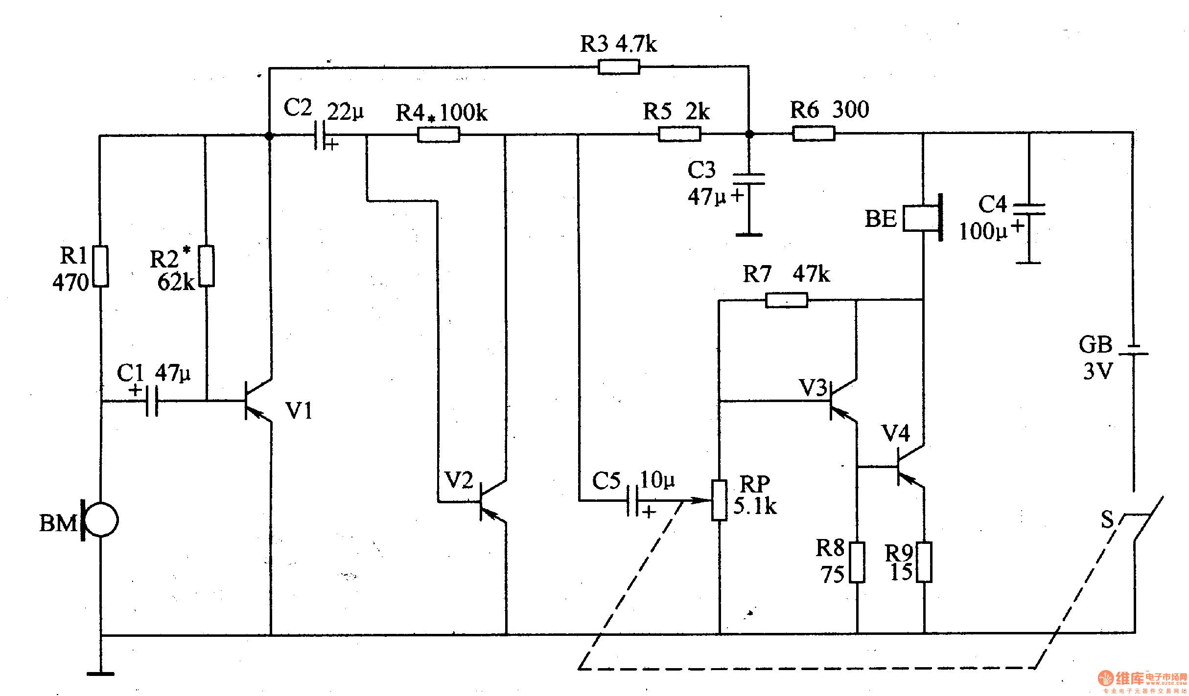
The memory enhancer introduced in this example is actually a "distraction reader", which first converts the user's voice into an electrical signal through a microphone, then multi-level audio amplification, and finally the amplified sound signal through the earphone. Played out so that the user can clearly hear the pronunciation of the person and concentrate, which helps to enhance the memory.
Circuit Operation Principle The memory booster circuit consists of a microphone (microphone) BM, a three-stage audio amplifier circuit, and headphones, as shown in Figure 9-76.

The first-stage audio amplifying circuit is composed of a transistor V1 and a resistor Rl-R3, capacitors C1 and C2; the second-stage audio amplifying circuit is composed of a transistor V2 and resistors R4 and R5, capacitors C2 and C5; and a third-stage audio amplifying circuit It is composed of transistors V3 and V4, resistors R7-R9, potentiometer RP, and the like.
After the sound signal is converted into an electrical signal by the microphone BM, it is coupled to the base (b pole) of V1 via the capacitor C1, and the signal amplified by the V1 buffer is output from the collector (c pole) of V1 and coupled to V2 via the capacitor C2. At the base, the amplified V2 audio signal is applied to the base of V3 via C5 and RP1. After V3 and V4 are combined and amplified, the headphone BE is driven to emit a loud sound.
Adjusting the resistance of the RP can change the volume of the sound volume of the headphones.
Component selection
Rl-R5 and R7-R9 select 1/8W carbon membrane resistor for use; R6 selects 1/4W carbon membrane resistor for use.
The RP uses a small potentiometer with a switch.
Cl-C5 selects aluminum electrolytic capacitors with a withstand voltage of 1 OV.
Vl-V3 selects 3AX3l type é”—PNP transistor for use; V4 selects 3AX81 type é”—PNP transistor for use.
The BM uses an electret microphone for the recorder.
The BE can be used in series with two 8Ω earphones, or the left and right channels of a normal headphone can be used in series.
After the working current adjustment circuit is installed, the working current of the collector of each amplifier should be adjusted. First, a current meter is placed in the collector loop of V1, and then the resistor R7 is adjusted so that the collector current of V1 is 0.4-0.6 mA.
In the collector circuit of V2, the current meter is connected, and the resistance of R4 is adjusted so that the collector current of V2 is 0.6-0.8 mA.
Disconnect the earphone from the circuit. After connecting the ammeter between the collector of V3 and V4 and the negative pole of the power supply, adjust the resistance of R7 so ​​that the collector current of the composite tube (V3 and V4) is 2.4-3 mA.
Circuit Operation Principle The memory booster circuit consists of a microphone (microphone) BM, a three-stage audio amplifier circuit, and headphones, as shown in Figure 9-76.

The first-stage audio amplifying circuit is composed of a transistor V1 and a resistor Rl-R3, capacitors C1 and C2; the second-stage audio amplifying circuit is composed of a transistor V2 and resistors R4 and R5, capacitors C2 and C5; and a third-stage audio amplifying circuit It is composed of transistors V3 and V4, resistors R7-R9, potentiometer RP, and the like.
After the sound signal is converted into an electrical signal by the microphone BM, it is coupled to the base (b pole) of V1 via the capacitor C1, and the signal amplified by the V1 buffer is output from the collector (c pole) of V1 and coupled to V2 via the capacitor C2. At the base, the amplified V2 audio signal is applied to the base of V3 via C5 and RP1. After V3 and V4 are combined and amplified, the headphone BE is driven to emit a loud sound.
Adjusting the resistance of the RP can change the volume of the sound volume of the headphones.
Component selection
Rl-R5 and R7-R9 select 1/8W carbon membrane resistor for use; R6 selects 1/4W carbon membrane resistor for use.
The RP uses a small potentiometer with a switch.
Cl-C5 selects aluminum electrolytic capacitors with a withstand voltage of 1 OV.
Vl-V3 selects 3AX3l type é”—PNP transistor for use; V4 selects 3AX81 type é”—PNP transistor for use.
The BM uses an electret microphone for the recorder.
The BE can be used in series with two 8Ω earphones, or the left and right channels of a normal headphone can be used in series.
After the working current adjustment circuit is installed, the working current of the collector of each amplifier should be adjusted. First, a current meter is placed in the collector loop of V1, and then the resistor R7 is adjusted so that the collector current of V1 is 0.4-0.6 mA.
In the collector circuit of V2, the current meter is connected, and the resistance of R4 is adjusted so that the collector current of V2 is 0.6-0.8 mA.
Disconnect the earphone from the circuit. After connecting the ammeter between the collector of V3 and V4 and the negative pole of the power supply, adjust the resistance of R7 so ​​that the collector current of the composite tube (V3 and V4) is 2.4-3 mA.
10W Wireless Charger,Car Wireless Charger,10W Wireless Charger,15W Wireless Phone Charger
Comcn Electronics Limited , https://www.comencnspeaker.com
