With the increasing use of microcomputers in automobiles, not only has the performance and comfort of automobiles been improved, but the entire vehicle control system has become more and more complicated. Therefore, once the user's car breaks down due to a failure, the maintenance personnel can quickly find the faulty part and eliminate it, which becomes an important issue for the automobile manufacturer. In today's era, the automotive industry is a leader, and the convenience and speed of after-sales service will inevitably become the focus of competition. This requires enriching and improving the fault detection capability while enriching various functions of the vehicle, making the car safer and easier to maintain.
1 Automobile fault self-diagnosis technology Driven by market demand, automobile fault diagnosis technology and fault diagnosis equipment have been greatly developed, and automobile diagnosis has also developed as a specialized technology. The automobile fault self-diagnosis device generally includes an on-board fault self-diagnosis device and an automobile fault diagnostic device.
1.1 In-vehicle fault self-diagnosis device In 1976, General Motors Corporation of the United States introduced the world's first electronic ignition control system MISAR, which has a self-diagnosis function for diagnosing the microcomputer that controls the ignition timing of the engine, the engine cooling water temperature and the battery voltage. When the input signal is equal, the alarm indicator lights when an abnormal condition occurs. With the development of automotive electronics technology, the fault self-diagnosis system has been able to monitor each sensor, actuator and ECU itself, and can judge and distinguish the fault type, and store it in the form of fault code for the maintenance personnel to use the special fault code. The reading device reads. The fault self-diagnosis technology is not only used in the engine electronic control system, but also widely used in the microcomputer control unit of the automatic transmission, the anti-lock brake device, the airbag and the like. The world's major car companies have promoted this technology and developed fault code readout settings for their respective models. This brings great convenience to the user in the timely detection of faults in the operation of the car and the query of the faults in the repair of the car.
1.2 Car Fault Diagnosis Instrument The car fault diagnosis instrument is used in conjunction with the on-board fault self-diagnosis system. In essence, it is equivalent to the terminal device of the self-diagnosis system and plays the role of human-computer interaction. With the development of microcomputer technology, the functions that the fault diagnosis instrument can complete are becoming more and more abundant.
· Display the fault code, display the location where the fault occurred, the method of inspection, the standard data of the test, etc., and print the above information;
· Clear the fault code;
· The display of real-time status data of the vehicle operation, the maintenance personnel can find out the cause of the failure by analyzing the direction and size of the data deviation from the standard data against the standard data;
· Issue a command to the ECU to force the action of the actuator to see if the actuator is working properly;
• Store status data and fault information for vehicle operation and output to a personal computer or diagnostic expert system.
2 Fault Diagnosis Communication Interface OBD-II Standard Introduction The previous fault diagnosis tools were developed by each vehicle manufacturer or instrument manufacturer. The diagnostic interfaces and communication methods are different and cannot be used interchangeably. Take the diagnostic socket as an example. Ford has 7 pins and 25 pins. The Mercedes-Benz has a round 9-pin, 38-pin, rectangular 16-pin and so on. This kind of individual situation not only brings trouble to the maintenance work, but also increases the maintenance cost and personnel training costs, which in turn affects the global sales of the products.
Since 1987, the California Department of Atmospheric Resources (CARB) has mandated that on-board fault self-diagnosis systems must be able to monitor automotive exhaust components. In 1994, CARB enacted stricter emission control regulations that stipulated that exhaust-related components must communicate with a diagnostic tool called a universal scanning tool. At the same time, the US Environmental Agency (EPA) has also taken corresponding measures to promote the use throughout the United States. Under the requirements of CARB, the American Society of Automotive Engineers (SAE) further promoted the standardization work related to the fault diagnosis instrument and formed the OBD-II standard for the diagnostic instrument interface.
OBD-II is the abbreviation of ON-BOARD DIAGNOSITICS, which is the second-generation on-board computer diagnostic system. It represents the technical level of most of the current diagnostic instruments. It can be said to be a practical standard and thus supported by automobile manufacturers. Its main features are:
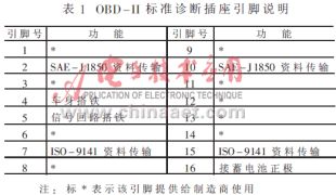
• The diagnostic socket is unified into a 16-pin socket and is installed under the cab dashboard. The diagnostic socket is shown in Figure 1, and the pin definition is shown in Table 1.
· Serial data communication protocol adopts ISO9141 and SAE standards;
· Has a uniform 5-digit fault code. For example, P1352, the first English letter represents the controller under test, such as P for the engine computer controller (Power), B for the body computer controller (Boby), C for the chassis computer controller (Chassis), the second word represents The manufacturer, the third word represents the fault range code defined by SAE, and the last two words represent the original fault code;
· It has the function of directly reading and clearing the fault code with the diagnostic instrument;
· With driving record function, it can record relevant data during the driving process of the vehicle;
• A function that remembers and redisplays fault information. 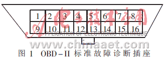
This article refers to the address: http://
3 VAG1551 Function Introduction VAG1551 is a general-purpose automotive electronic system maintenance and diagnostic instrument for Volkswagen Group's internal after-sales service. It can read the diagnostic and test information of more than ten automotive electronic systems such as electronically controlled gasoline injection engines and automatic transmissions. For example, when repairing engine electronics, maintenance personnel can use it to read fault codes, and also can read engine real-time status parameters such as speed, water temperature, load, voltage, fuel injection time, etc., and also can be executed to various actuators of the ECU. Issue an enforcement command. When operating, connect the diagnostic unit to the diagnostic socket before the car's gear. The diagnostic socket complies with the OBD-II standard, in which pin 4 is the body ground, pin 7 is BDDIAKM (ie K line), pin 16 is the battery positive, and the remaining pins are all empty.
When using, first input the address code of the detection object. If the engine electronics is 01, then select the function, such as the function number of the query fault code is 02. See the relevant materials for specific methods of use.
The pin 7 of the diagnostic socket should be connected to the K line of each electronic control system on the vehicle. The diagnostic instrument can only communicate with one electronic control system at a time. Initially, the diagnostic device transmits the identification information (ie address code) through the K line in a broadcast manner, but only the electronic control system corresponding to the address code responds, so the diagnostic device and the electronic control system start to communicate, and the remaining systems Still in standby.
4 VAG1551 and engine electronic communication rules Preliminary due to the limitations of the conditions, this paper only studied the communication law of VAG1551 and Engine Electronics, and the ECU is limited to MOTRONIC M1.54P.
4.1 Using the serial port of the computer to take into account that the communication code of the VAG1551 and the ECU is a serial port signal, but the voltage of the serial port signal of the RS-232 standard is different. The "1" of the standard serial port signal is represented by -12V, and the "0" is represented by +12V. The "0" of the K line is represented by 0 to 1.3V, and the "1" is represented by 12V. Therefore, by designing a conversion card and converting the serial signal of the K line into a standard serial port signal, the VAG1551 can be intercepted by using the computer serial port. Communication codes with the ECU to study their communication rules. In addition to the level conversion function, the conversion card has a working frequency greater than 10 kHz, and the input resistance is large, which does not affect the communication between the VAG1551 and the ECU. Figure 2 shows the schematic diagram of the computer serial port truncation code. 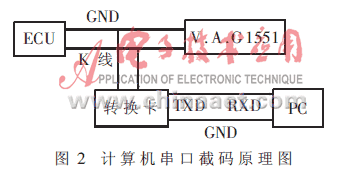
The efficiency of using the conversion card is very high. The file obtained by each code is also small, about 1Kbytes, and can be read directly under the editing software, which is very convenient to use. The task below is to perform a truncation study on each function of the VAG1551 one by one to find out how they communicate under various operating conditions of the engine.
4.2 Analysis of the truncated data The data obtained by the VAG1551 during the communication of the function number 04 data block 000 is shown below, and a simple analysis is performed.
After the VAG1551 issues the address code, the ECU answers the controller version number, as shown in Table 2. 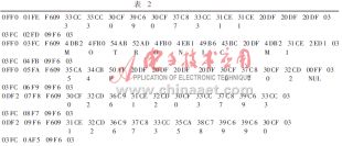
Next, the two parties send a handshake signal to not interrupt the contact, and the ECU waits for the VAG1551 to issue an instruction:
03FC 0BF4 09F6 03
03FC 0CF3 09F6 03
03FC 0DF2 09F6 03
The VAG1551 issues the function 04-000 command, the ECU answers the corresponding information, and both parties keep asking questions until the user enters "→":
03FC 0EF1 11EE 03
0DF2 0FF0 F40B 659A A25D C837 1DE2 807F 5BA4 02FD 00FF 07F8 1FE0 03
03FC 10EF 11EE 03
0DF2 11EE F40B 659A A25D C837 1DE2 807F 5BA4 02FD 00FF 07F8 1EE1 03
03FC 12ED 11EE 03
0DF2 13EC F40B 659A A25D C837 1DE2 807F 5BA4 02FD 00FF 07F8 1EE1 03
Then the two parties wait for another handshake until the user issues an end command and the communication ends:
03FC 14EB 09F6 03
03FC 15EA 09F6 03
03FC 16E9 09F6 03
03FC 17E8 09F6 03
03FC 18E7 06F9 03
In these data, a special code can also be found, that is, the second data of each line. After analysis, this is a digital number, and each message sent by the communication party is incremented by one. And you can see that the command issued by VAG1551 is 11 when the function number is 0, and the end command is 06. The verification method adopted by both parties is the inverse code, that is, the receiver sends the inverse of the received code, and the sender considers that the other party receives the correct code after receiving the reverse code (for example, VAG1551 sends 06, ECU answers F9).
After many experiments, you can know the communication code of VAG1551 in detecting various functions of engine electronics (including reading fault code and eliminating fault code). These communication codes lay a solid foundation for the development of VAG1551 compatible vehicle fault diagnosis instrument.
In addition to reading the fault code, VAG1551 can also read real-time engine parameters such as speed, water temperature, load, voltage, fuel injection time, etc. After data analysis, VAG1551 does not directly display these parameters, but puts these parameters. The code is displayed after some conversion.
5 Development of the VAG1551 compatible computer diagnostic system VAG1551 is a German-made instrument, which is expensive, and some VAG1551 are German display, which is inconvenient to use, so it is necessary to develop a car diagnostic instrument compatible with it. The general-purpose computer system has a standard serial port, and the programming space is large and easy to debug, so the computer diagnostic system can be developed first.
5.1 Hardware Part Similarly, the serial port of the computer system is not compatible with the serial port of the VAG1551. Therefore, it is necessary to design an adapter card. Unlike the above conversion card, the data stream of the adapter card is bidirectional, but the communication is half-duplex. Therefore, an analog switch should be added to the adapter card to isolate both data. Figure 3 shows the schematic of the adapter card. 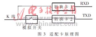
When the computer sends out the data, the analog switch is turned on, the data is sent to the ECU through the K line, and the data is sent back to the computer. When the computer receives the data, it can be determined that the data has been sent. At this time, the analog switch should be turned off immediately, waiting for the ECU. Reply. In this process, the off time of the analog switch is a key. If the analog switch is turned off early (that is, the computer serial code has not been sent yet), the data received by the ECU will be wrong. If the analog switch is turned off (that is, the ECU has sent data) Will affect the computer to receive data.
5.2 The software part of the software adopts modular design, that is, the main program is programmed into one module. Each function of VAG1551 is compiled into a module, and each module is assembled and then connected into an executable file. There are several advantages to using modular programming:
(1) Each module has a clear task and is easy to understand;
(2) A single module is easy to write and debug;
(3) Facilitating the maintenance and modification of the program;
(4) To increase the function of the diagnostic instrument, just add the corresponding module.
When programming, you can use the method of gradually increasing the function, that is, first edit the main module and the first function module. After the debugging is successful, connect the second function module and debug again until all is completed.
After a period of debugging, the author has initially developed a computer diagnostic system compatible with the VAG1551. Of course, it is currently limited to the diagnosis of M1.54P engine electronics. Figure 4 shows the main block diagram of the software. 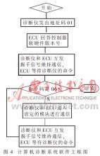
The method described in this paper is to develop a VAG1551-compatible car fault diagnosis instrument by studying the external communication rules of VAG1551 and ECU. It should be said that the main function can be consistent with VAG1551, but there are still differences in details. And this article has not touched on another very important aspect, that is, how the VAG1551 and the ECU solve the error problem, that is, what action will be taken when the VAG1551 receives the ECU's confirmation code is wrong. These questions are still waiting for us to do further research.
1. 4-IN-1 MOBILE CONTROLLER mobile game controller which combines Gaming Triggers, Silent cooling fan, Emergency charging bank and charging cable in order to improving and promoting your immersive gaming experience, which also could help you get a good score in the shooting games.
2. COOLING FUNCTION & EMERGENCY CHARGING .mobile game controller with a built-in silent cooling fan and a high quality 1200mAh battery, the built-in silent cooling fan could help cooling your hot mobile phone, and 1200mAh battery also could help charging your mobil phone when your mobile phone is almost powered off.
3. PLAYING WITH 4 FINGERS - Customize the button as you like, you can play shooting games with 6 fingers, such as aiming, shooting, moving, squatting, left tilted head and right tilted head at the same time. In addition, the turnover button can help you customize icon more easily.
4. SUPPORTED DEVICES & GAMES - Suitable for the majority of mobile phone, the max stretch width is 3.9inchwhich could compatible with the majority of shooting games, such as Rules of Survival, Knives Out, Survivor Royale, Critical Ops, etc.
5. EXCELLENT SERVICE - If our Mobile Game Controller have any problems, please contact us by email, we will replace the defective product for you as soon as possible, and we offer 12 months warranty.
Mobile Game Controller,Game Pubg Controller,Gamepad Equipment,Game Shooter Controller
MICROBITS TECHNOLOGY LIMITED , https://www.microbitstrade.com
