
The currently widely used vehicle bus technologies (such as CAN, VAN, LIN and other buses) are unable to meet the requirements due to the lack of certainty, synchronization and fault tolerance mechanisms. The FlexRay Alliance has promoted the standardization of FlexRay, making it a new generation of automotive internal networks letter of agreement. FlexRay focuses on some of the core requirements of today's automotive industry, including faster data rates, more flexible data communications, more comprehensive topology selection, and fault-tolerant computing.
Each access point in the FlexRay bus is called a node. The node is mainly composed of four parts: a power supply system (Power Supply), a bus driver (Bus Driver), a communication controller (CommunicaTIon Controller) and a host (Host) with the FlexRay communication protocol fixed. The communication controller is the core device of the communication node. Its main functions are media access control, clock synchronization, codec, protocol operation control, etc. The media access control function is the core function of the communication controller. It solves the way data enters the FlexRay communication controller, and prepares the time and data for the codec function of the communication controller.
This paper presents a design method for the media access control of the FlexRay communication controller. This method directly accesses the memory, greatly reducing the time to obtain the configuration; the design is more streamlined and can ensure the stability of the communication.
1 Design of media access control
The method for implementing media access control based on memory in this paper includes the following steps: First, all sub-modules of the media access control module work in a unified clock domain, and the user writes configuration information related to media access control into memory; Then, each sub-module of the media access control reads the information directly from the memory. The principle diagram of media access control is shown in Figure 1.
The clock generation module forms the clock cycle required by the system for the minimum clock cycle generated by the controller crystal according to the user's configuration information; the control module further divides the clock cycle into 4 independent segments according to the user configuration information, that is, static Segment, dynamic segment, symbol window, network idle segment; timer module implements timing function according to user configuration information, used to record the time required for media access control.
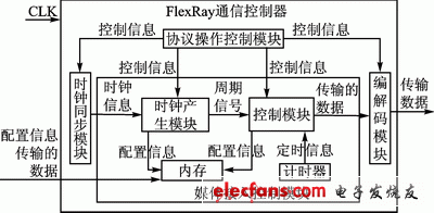
Figure 1 Schematic diagram of media access control
1.1 Clock generation module
The clock generation module implements the clock cycle required for media access control, prepares the time for the codec function, and transmits this information to the control module. The module first reads the required configuration information from the memory, mainly gMacroPerCycle, gdStaTIcSlot, pMicroPerCycle. The clock generation module performs initialization operations based on these configuration information, and then waits for the minimum clock tick of the crystal oscillator (vMicroTIck). When the minimum clock cycle is greater than or equal to pMicroPerCycle / (gMacroPerCycle-1), the module generates a cycle.
The processing flow of the clock generation module is shown in Figure 2.
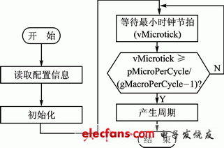
Figure 2 Processing flow of the clock generation module
Motion Control Sensor is an original part that converts the change of non-electricity (such as speed, pressure) into electric quantity. According to the converted non-electricity, it can be divided into pressure sensor, speed sensor, temperature sensor, etc. It is a measurement, control instrument and Parts and accessories of equipment.
Absolute Rotary Encoder,Absolute Linear Encoder,Absolute Optical Encoder,Absolute Position Encoder
Changchun Guangxing Sensing Technology Co.LTD , https://www.gx-encoder.com