Massive MIMO (large-scale antenna) technology is one of the key technologies of 4.5G/5G, and the global communication industry is very concerned about Massive MIMO technology. China Mobile and Softbank Japan have launched TD-LTE Massive MIMO technology. Operators such as China Unicom, China Telecom and Telkomsel completed the FDD Massive MIMO field test. Massive MIMO was used as the key technology in the first phase of China's 5G trial, and five vendors including Huawei, ZTE and Ericsson participated in the test. 3GPP has already supported Massive MIMO as one of the important features since the R13 release.
Massive MIMO technology enables larger wireless data traffic and connection reliability using a large number of array antennas (such as 64/128/256, etc.) on the base transceiver station. Compared with previous single/dual-polarized antennas and 4/8-channel antennas, large-scale antenna technology can improve spectrum and energy utilization efficiency through different dimensions (space, time domain, frequency domain, polarization domain, etc.); 3D The shaping and channel estimation techniques can adaptively adjust the phase and power of each antenna element, significantly improve the beam pointing accuracy of the system, and concentrate the signal strength on specific pointing areas and specific user groups, which can significantly enhance the user signal. Reducing self-interference and neighboring interference in the cell is an excellent technology to improve the carrier-to-interference ratio of the user signal.
How to evaluate Massive MIMO technology, what test indicators and test methods are used, and how to measure Massive MIMO technology fairly and efficiently? This is also the current communication technology industry is very concerned about the issue.
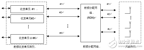
2. Massive MIMO system architectureThe active antenna base station architecture supporting Massive MIMO is represented by three main functional modules: a radio frequency transceiver unit array, a radio frequency distribution network, and a multi-antenna array.
The RF transceiver unit array includes a plurality of transmitting units and receiving units. The transmitting unit obtains the baseband input and provides a radio frequency transmission output, and the radio frequency transmission output is distributed to the antenna array through the radio frequency distribution network, and the receiving unit performs the operation opposite to the operation of the transmitting unit. The RDN distributes the output signals to the corresponding antenna paths and antenna elements and distributes the input signals of the antennas in opposite directions.
The RDN may include a simple one-to-one mapping between the transmitting unit (or receiving unit) and the passive antenna array. In this case, the radio distribution network will be a logical entity but not necessarily a physical entity.
Antenna arrays can include various implementations and configurations such as polarization, spatial separation, and the like.
The physical location of the RF transceiver unit array, the RF distribution network, and the antenna array may differ from the logical representation of the following figure, depending on the implementation.

Figure 1 Active antenna base station architecture supporting MassiveMIMO
3, Massive MIMO test technology3.1 The evolution of antenna systems challenges test technology
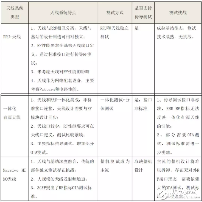
With the development of antenna systems to modernization, especially the evolution of 5G, the integrated base station active antenna system (AAS) form has gradually become the mainstream, the number of channels is increasing, and the active antenna connection mode is also simplified, RU and antenna. Highly integrated, RF indicators are no longer limited to traditional RU conduction testing. OTA testing will be the direction of future test evolution, and will also bring great testing challenges.
Table 1 Evolution of antenna systems challenges test technology

3.2 Test signal modulation

Figure 2 Test signal modulation
Active antennas work in various service carrier states to achieve network coverage. To test the performance of active antennas, the test system needs to have the following test capabilities:
1. The test system needs to support the amplitude and phase test of the service signal. Especially the existence of large bandwidth signal testing;
2. The pattern test signal pattern needs to be discussed and defined.
3.3 Antenna beam diversification

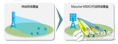
Figure 3 Schematic diagram of Massive MIMO antenna network coverage
In the scenario where the antenna beam radiation characteristics tend to be complex:
1: How to accurately estimate the beam pointing accuracy, side lobes, lobe width, etc. of the antenna service;
2: How to select a multi-beam test scenario;
3: Test efficiency problem of multi-beam antenna;
4: Evaluate coverage performance for how multiple beams pass two-dimensional radiation characteristics.
Test recommendations:
1: It is necessary to evaluate the requirements of active antennas, especially Massive MIMO antennas, under two main planes; research needs to define 3D radiation index requirements;
2: Evaluate multi-beam radiation performance under real service signals and establish a test case set.
3.4 Communication antenna frequency band high frequency
High frequency (millimeter wave) coverage has always been an industry challenge, and Massive MIMO is a good solution to this problem. As an extended frequency band of 5G, it provides capacity guarantee.
TO-220 Transistor Outline Package is a type of in-line package often used in high-power transistors and small and medium-sized integrated circuits.
It not only plays the role of mounting, fixing, sealing, protecting the chip and enhancing the electrothermal performance, but also connects to the pins of the package shell with wires through the contacts on the chip, and these pins pass through the wires on the printed circuit board. Connect with other devices to realize the connection between the internal chip and the external circuit.Because the chip must be isolated from the outside world to prevent impurities in the air from corroding the chip circuit and causing electrical performance degradation. On the other hand, the packaged chip is also easier to install and transport.
TO-220 package is a kind of in-line package that is often used for fast recovery diodes. TO-220AC represents a single tube with only two pins and only one chip inside.
The diodes are packaged in TO-220AC and can be used in switch mode power supplies (SMPS), power factor correction (PFC), engine drives, photovoltaic inverters, uninterruptible power supplies, wind engines, train traction systems, electric vehicles and other fields.
TO-220 package,Super Fast Recovery Rectifiers,Fast Rectifiers Diode,Ultra Fast Rectifiers
Changzhou Changyuan Electronic Co., Ltd. , https://www.cydiode.com
