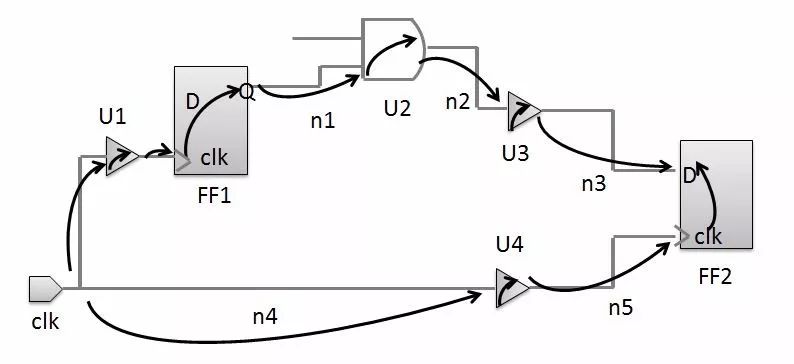
The basic concept of the timing we are going to introduce today is Timing arc, Chinese name timing arc. This is the most basic component of timing calculation. In yesterday's lib library introduction, most of the timing information is presented in Timing arc. If there is a causal relationship between the two pins on timing, we call this timing relationship Timing arc, which is mainly divided into defining timing delay and defining timing checking. Why is it called a timing arc? Because it is often represented by a curved line segment in the timing diagram. As shown in the following figure: The timing arc of the cell is defined in lib, there is no timing arc between nets, and its delay is calculated by RC parameters.

Timing arc with timing delay: There are the following
Combinational Timing Arc
Edge Timing Arc
Preset and Clear Timing Arc
Three State Enable & Disable Timing Arc
Timing arc for timing check: there are the following
Setup Timing Arc
Hold Timing Arc
Recovery Timing Arc
Removal Timing Arc
Width Timing Arc
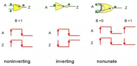
First look at the Combinational Timing Arc, the Combinational Timing Arc is the most basic Timing Arc. Timing Arc belongs to this category if not specified. As shown in the figure below, the delay time from a specific input to a specific output (A to Z) is defined. Combinational Timing Arc has three types of Sense: inverting (or negative unate), non-inverting (or positive unate), and non-unate. When Timing Arc's specific output (below Z) signal changes direction and the specific input (bottom A) signal changes direction (such as input changes from 0 to 1 and output changes from 1 to 0), then Timing Arc is inverting sense. Conversely, if the output input signal changes direction, the Timing Arc is non-inverting sense. This Timing Arc is non-unate when a particular output cannot be individually determined by a particular input.

Other Timing Arc instructions are as follows.
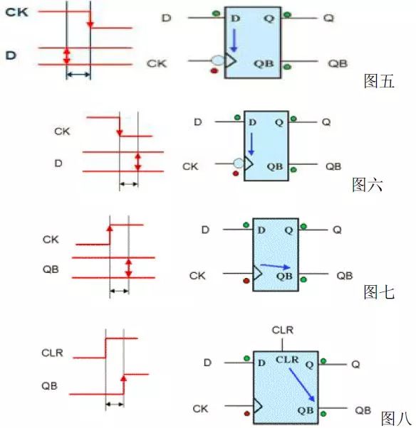
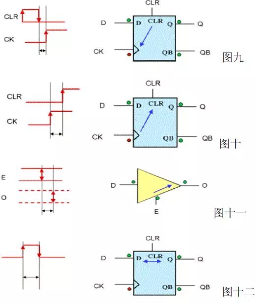
Setup Timing Arc: Defines the Setup Time required for Sequential Cells (such as Flip-Flop, Latch, etc.) and classifies them according to whether the Clock rises or falls (Figure 5). Hold Timing Arc: Defines the Hold Time required for the timing component, which is divided into 2 categories according to the rise or fall of the Clock (Figure 6). Edge Timing Arc: Defines the delay time of the timing component Clock Active Edge to data output, divided into 2 categories according to the rise or fall of the Clock (Figure 7). Preset and Clear Timing Arc: Defines the timing component clear signal (the speed at which data is cleared after Preset or Clear occurs, depending on whether the clear signal rises or falls and is Preset or Clear divided into 4 categories (Figure 8). This Timing Arc will usually be Canceled, because it will cause the signal path to generate a loop, which is not allowed for the STA. Recovery Timing Arc: Before defining the timing component Clock Active Edge, clear the time when the signal is not allowed to start, according to the rise or fall of the Clock is divided into 2 Class (Figure 9).Removal Timing Arc: After defining the sequence component Clock Active Edge, clear the time when the signal is not allowed to start, according to the rise or fall of the Clock, divided into 2 categories (Figure 10). Three State Enable & Disable Timing Arc: Definition Tri-State component enable signal (Enable) to output delay time, according to Enable or Disable divided into 2 categories (Figure 11) Width Timing Arc: defines the minimum time that the signal needs to remain stable, according to the signal maintained at 0 or 1 The level of the class is divided into 2 categories (Figure 12)


Specialized Slip Ring,Slip Ring Rotary Joint,Slip Ring Induction Motor Rotor,Induction Motor Slip Ring
Dongguan Oubaibo Technology Co., Ltd. , https://www.sliprob.com
