1. The design of GTR drive circuit requires GTR base drive mode to directly affect its working state, which can improve or degrade some characteristic parameters. For example, overdrive accelerates turn-on and reduces turn-on loss, but it is unfavorable for shutdown. Turn off the loss. Whether the drive circuit has a fast protection function is an important condition for the GTR to be damaged after overvoltage or overcurrent. GTR has low heat capacity and poor overload capability. It is impossible to protect GTR at all by using fast fuses and overcurrent relays. Therefore, the method of cutting off the main circuit is no longer used, but the method of quickly cutting off the base control signal is used for protection. This translates the protection measures into two aspects of how to detect fault conditions in a timely and accurate manner and how to quickly and reliably block the base drive signal.
(1) Considerations for designing the base driver circuit Three aspects that must be considered when designing the base driver circuit are: optimized drive characteristics, drive mode, and automatic fast protection.
1 Optimized drive characteristics Optimized drive characteristics are to control the switching process of the device with an ideal base drive current waveform to ensure high switching speed and reduce switching losses. The optimized base drive current waveform is similar to the GTO gate drive current waveform.
2 Drive mode The drive method has different classification methods according to different situations. Here, the driving mode refers to the connection mode between the driving circuit and the main circuit, and it has two kinds of driving modes: direct and isolated: the direct driving mode is divided into a simple driving, a push-pull driving, and a saturated driving; the isolated driving mode Divided into photoelectric isolation and electromagnetic isolation.
3 Automatic fast protection function In the event of a fault, in order to achieve fast and automatic cut off of the base drive signal to avoid damage to the GTR, fast protection measures must be taken. The types of protection are generally anti-saturation, anti-saturation, over-current, over-voltage, over-temperature and pulse limiting.
(2) The base drive circuit of the base drive circuit GTR has various forms such as a constant current drive circuit, an anti-saturation drive circuit, a fixed reverse bias complementary drive circuit, a proportional drive circuit, and an integrated drive circuit. The constant current driving circuit means that the base current of the GTR is kept constant and does not change with the collector current. The anti-saturation drive circuit is also called the Beck clamp circuit. Its function is to make the GTR in the quasi-saturation state when it is turned on, so that it does not enter the amplification region and the deep saturation region. When it is turned off, applying a certain negative base current is beneficial to reduce. Turn-off time and turn-off loss. The fixed reverse bias complementary driving circuit is composed of a complementary output circuit with positive and negative dual power supply. When the circuit output is positive, the GTR is turned on; when the circuit output is negative, the transmitting junction is reverse biased, and the excess in the base region The carriers are quickly extracted and the tube is quickly shut off. The proportional drive circuit is such that the base current of the GTR is proportional to the change of the collector current, ensuring that the saturation depth of the device is substantially the same under different load conditions. The integrated driving circuit overcomes the above disadvantages of many circuit components, complicated circuits, poor stability, and inconvenient use. Representative devices are the UAA4003 from THOMSON and the M57215BL from Mitsubishi.
There are many types of driving circuits for 1GTR. The driving circuit of a discrete component GTR is described below, as shown in FIG. The circuit consists of two parts: electrical isolation and transistor amplification. The diode VD2 and the potential compensation diode VD3 in the circuit form a Beck clamp anti-saturation circuit, which makes the GTR in a critical saturation state when it is turned on. When the load is light, if the emitter current of V5 is fully injected into V, V will be over-saturated, and the desaturation time will be prolonged when turned off. With the Beck circuit, when V oversaturation causes the collector potential to be lower than the base potential, VD2 will automatically turn on, causing excess drive current to flow into the collector, maintaining Ubc≈0. In this way, V is always in critical saturation when it is turned on. C2 in the figure is the capacitor for the accelerated turn-on process, and R5 is short-circuited by C2 when turned on. In this way, the overshoot of the drive current can be achieved, while increasing the steepness of the leading edge and speeding up the turn-on. In addition, when V5 is turned on, C2 is charged, and the polarity of charging is left and right negative, preparing for the turn-off of GTR. When V5 turns off V6, the charging voltage on C2 applies a counter voltage to the emitter junction of the V-tube, so that the GTR is quickly turned off. 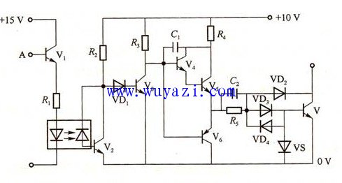
There are many types of 2GTR integrated drive circuits. Here are a few simple cases:
HL202 is a domestic dual-in-line, 20-pin GTR integrated drive circuit with a differential transformer for signal isolation, Beck clamp de-saturation, and negative supply undervoltage protection. Operating power supply voltage +8~+10V and -5.5V~ -7V, the maximum output current is greater than 2.5A, can drive GTR below 100A.
UAA4003 is a dual-in-line, 16-pin GTR integrated driver circuit that can achieve optimal driving and perfect protection for the driven GTR, ensuring GTR operation in critical saturation ideal state, and has its own PWM pulse forming unit, especially suitable for DC. Chopper system.
The M57215BL is a dual-in-line, 8-pin GTR integrated driver circuit. It operates from a single-supply negative-bias voltage and can drive a GTR module of 50A or less. It can drive a GTR module of 75~400A or more.
Permanent magnet Dc Motor is composed of stator magnetic pole, rotor, brush, case and so on. Stator magnetic pole is made of permanent magnet (permanent magnet steel), ferrite, alnico, ndfeb and other materials, and the rotor is generally made of silicon steel laminated. Enameled wire is wound between two slots in the rotor core (three slots are provided with three windings), and its joints are separately welded on the metal sheet of the commutator. Electric brush is a conductive part connecting power supply and rotor winding. Permanent magnet motor brush USES single metal sheet or metallic graphite brush, electrochemical graphite brush.Permanent magnet Gear Motor is established using permanent magnet magnetic field of a dc motor. Permanent magnet gear motor is widely used in various kinds of portable electronic equipment or apparatus
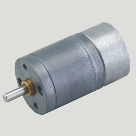
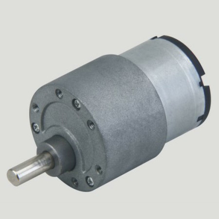
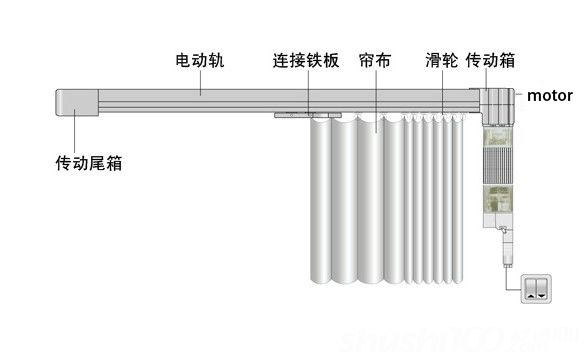
precision instruments and meters,automobile industry, medical equipment, consumer electronics, household appliances, electric glass doors and Windows,etc., wide application range,,Permanent Magnet Gear Motor is usually used in small power occasion.

Features: permanent
magnet gear motor is a kind of rectangular pulse wave, sine wave current, in the form of hybrid permanent magnet motor. Simple structure, high reliability and high efficiency.
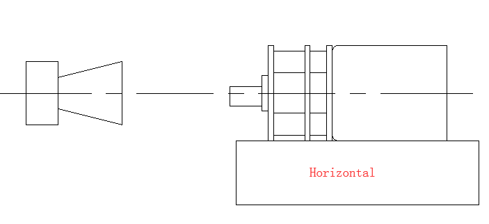
Method of use: the best stable in horizontal plane, installed on the permanent magnet gear motor output shaft parts, cannot use a hammer to knock,knock prone to press into the permanent magnet gear motor drive, may cause damage to internal components, and cannot be used in the case of blocked.
Operating temperature range:
permanent magnet gear motor should be used at a temperature of -10~60℃.
The figures stated in the catalog specifications are based on use at ordinary room temperature catalog specifications re based on use at ordinary room temperature (approximately20~25℃.
If a geared motor is used outside the prescribed temperature range,the grease on the gearhead area will become unable to function normally and the motor will become unable to start.Depending on the temperature conditions ,it may be possible to deal with them by changing the grease of the motor's parts.Please feel free to consult with us about this.
Storage temperature range:
permanent magnet gear motor should be stored ta a temperature of -15~65℃.
In case of storage outside this range,the grease on the gearhead area will become unable to function normally and the motor will become unable to start.
Service life:
The longevity of permanent magnet gear motor is greatly affected by the load conditions , the mode of operation,the environment of use ,etc.Therefore,it is necessary to check the conditions under which the product will actually be used .The following conditions will have a negative effect on longevity.Please consult with us should any of them apply.
â—Use with a load that exceeds the rated torque
â—Frequent starting
â—Momentary reversals of turning direction
â—Impact loads
â—Long-term continuous operation
â—Forced turning using the output shaft
â—Use in which the permitted overhang load or the permitted thrust load is exceeded
â—A pulse drive ,e.g.,a short break,counter electromotive force,PWM control
â—Use of a voltage that is nonstandard as regards the rated voltage
â—Use outside the prescribed temperature or relative-humidity range,or in a special environment.
â—Please consult with us about these or any other conditions of use that may apply,so that we can be sure that you select the most appropriate model.
when it come to volume production,we're a major player as well .each month,we rurn out 600000 units,all of which are compliant with the rohs directive.Have any questions or special needed, please contact us, we have the engineer group and best sales department to service to you Looking forward to your inquiry. Welcome to our factory.

Permanent Magnet Gear Motor,Permanent Magnet Motor With Gear,Permanent Magnet Gear Motor 5V,Permanent Magnet Stepper Gear Motor
Shenzhen Shunchang Motor Co., LTD. , https://www.scgearmotor.com
