It is especially important to improve the design of the single-chip system and improve the reliability of the system. For the single-chip system, there are two kinds of interference factors. One is the interference generated by the external environment of the system and other electrical equipment. It affects the normal operation of the single-chip system through conduction and radiation. The second is from the system, from the system structure. The manufacturing process and other decisions and internal components interfere with the operation, and the transmission of the address, power line, signal line, distributed capacitance, etc., affects the working state of the switching power supply module system.
1. What is the source of interference?
The source of interference is the component, device, or signal that produces the interference. The resulting interference includes:
(1) Electromagnetic interference, such as relay switch start-up, electrostatic discharge, grid voltage fluctuations, etc., may cause different levels of transient surge voltage, which may cause burnt-out of IC and semiconductor device PN junction, breakdown of oxide layer, and the like.
(2) Human interference, such as mechanical vibration, relay contact jitter, electromagnetic coupling caused by component mounting and circuit board wiring, poor connector contact, virtual soldering, amplifier self-excitation, power supply ripple, etc.
(3) Environmental factors such as noise and ambient temperature and humidity, as well as changes in sunspots, space particle radiation, etc.
The misoperation caused by each device interference may occur once in a thousand times, even in tens of thousands, and only once in a million. Time is one day, one month, or even many years a year. But the serious consequences of the interference are unimaginable.
Here I will quote an episode:
"When I was doing welding machine in Zhenjiang, there was always a signal output from the welder at the moment of power-on. The frequency of occurrence was very high. The most serious one was almost pressing a customer's employee's finger. Then I thought about it. The method is to add a 50k pull-up resistor to the I/O port of the signal output. The problem is still there, but the frequency of the drop is reduced. Later, the 15k resistor is used again, and the problem is completely solved. ."
The interference signal source also follows Ohm's law. The more interference there is, the more it is related to the pull-up resistor used in the test. To find out how he solved it, you can read the following article:
[Topic] [MCU Weekly Argument] How to improve the anti-interference ability of the MCU? Do you understand?
2. What is the cause of the interference source?
Go back to the topic below,
The causes of MCU interference also include the propagation path, the use of sensitive devices, and the interference of the MCU.
The impact of interference on the microcontroller system is mainly transmitted in three ways, including:
(1) Input system. Under normal circumstances, the detection object of the on-board instrument of the switching power supply module is often a weak physical signal, which is composed of an amplified operational amplifier circuit and a high-precision A/D conversion circuit. If the serial interference occurs, the input analog signal will be distorted, and the digital signal will be wrong, resulting in an increase in the acquired data error.
(2) Output system. Once interfered, the output signals will be confusing and will not reflect the true output of the microcontroller system. However, the output circuits of general single-chip microcomputers have higher levels and are not susceptible to interference. It is necessary to pay attention to the interference effects on other circuits.
(3) CPU system. The interference is mainly caused by the internal clock and noise of the CPU. It can make the digital signal on the system bus of the single chip computer confuse, and the CPU gets the wrong address signal, causing the program to run or die, causing the output error and transmitting the error all the time. , causing the system to fail.
Sensitive device
In the on-board instrument microcontroller system, some easily interfered devices such as A/D, D/A converters, and weak signal amplifiers are also used, which is also an important cause of interference.
Three. Anti-interference technology and measures of single chip microcomputer
The circuit of the single-chip microcomputer system is complicated, and there are many reasons for the interference. Then, how should we prevent the interference of the single-chip microcomputer and improve the performance of the single-chip microcomputer and the anti-interference effect? Here are a few common anti-jamming measures:
1. Cut off the transmission route of interference
1) Increase the distance between interference sources (such as motors, relays) and sensitive devices (such as microcontrollers), isolate them with ground wire or add shields to sensitive devices.
2) The circuit board is reasonably partitioned, and the strong signal, weak signal, digital signal and analog signal circuit are reasonably arranged in different regions.
4) The ground wire of the MCU and the high-power device should be grounded separately to reduce mutual interference. High-power devices should be placed as close as possible to the edge of the board.
5) In the key places such as the I/O port of the MCU and the circuit board connection line, the anti-interference component can significantly improve the anti-interference performance of the circuit.
6) The crystal oscillator and the MCU pins are as close as possible. The clock area is isolated by the ground wire, and the crystal oscillator case is grounded and fixed.
2, try to use the anti-interference performance of the microcontroller
1), reduce the power supply noise inside the microcontroller
In the conventional digital integrated circuit design, the power terminal and the ground terminal are usually arranged on two sides of the symmetry. For example, the bottom left corner is ground and the upper left corner is power. This causes power supply noise to pass through the entire wafer. The improved method arranges the power supply and ground of the MCU on two adjacent pins, which not only reduces the current flowing through the entire silicon chip, but also facilitates designing the power supply decoupling capacitor on the printed circuit board to reduce system noise.
2), reduce the clock frequency
The clock circuit of the single-chip measurement and control system is a frequency-modulated noise source. It can not only interfere with the system, but also cause interference to the outside world, so that the electromagnetic compatibility detection of other systems cannot reach the standard. Under the premise of ensuring system reliability, selecting a single-chip microcomputer with a low clock frequency can reduce the noise of the system. Take the 8051 microcontroller as an example. When the shortest instruction week is 1US, the clock is 12MHZ. The same speed MOTOROLA compatible microcontroller manufacturers reduce the clock frequency to 1/3 without sacrificing the speed of operation. In particular, MOTOROLA's new 68HC08 series MCU uses internal phase-locked multiplier technology to divide the external clock to 32KHZ, while the internal bus speed is increased to 8MHZ or even higher.
3), EFT technology
With the development of ultra-large-scale integrated circuits, the anti-jamming technology inside the single-chip microcomputer is also constantly improving. MOTOROLA's new 68HC08 series single-chip microcomputer adopts EFT technology to further improve the anti-interference ability of the single-chip microcomputer. When the sine wave signal of the oscillation circuit is disturbed by the outside, some burrs will be superimposed on the waveform. If it is shaped by a Schmitt circuit, this glitch will become a clock signal that the trigger signal interferes with normal. But alternating the use of a Schmitt circuit and RC filtering can make such burrs inoperative, which is EFT technology.
3. Frequency jitter technology in single-chip measurement and control system
The frequency pull signal is superimposed on the random noise of the input signal, although the total noise of the conversion is increased, but the added noise is used to compensate the output digital quantization noise, so that the quantization error is no longer a function of the input signal but a jitter noise instant. The function of the value. Therefore, the correlation between the quantization noise and the input signal can be removed by using the frequency dither signal. The magnitude of the frequency pull signal is typically approximately 1/3 LSB rms. For example, in the case of no frequency pull, the quantization noise of the ADC output is a function of the amplitude of the instantaneous input signal. After the quantization pull, since the amplitude of the jitter signal does not depend on the input signal, the quantization noise is independent of the input signal, thereby eliminating the The ADC outputs harmonic components, but this comes at the cost of increased total noise. It should be pointed out that it is not necessary to actually apply the chattering noise at the input of the ADC. The thermal noise of the ground converter can also be used as the frequency jitter signal, but the ADC must have enough output bits to ensure that the input signal and the quantization noise can be removed. Correlation.
4, technology to prevent leakage current
The intelligent single-chip measurement and control system should be used under the conditions of clean, dry, ventilated and suitable ambient temperature. When the system is wet, the insulation resistance drops and leakage current is generated. The light measurement increases the measurement error and the control is not working; the heavy one will cause a moderate fault and damage the components. For example, when the printed board is wet, the input impedance of the A/D converter drops, the reading is not accurate, and it is accompanied by a hop count. This is also the main reason why some digital voltmeters do not work properly during the thunderstorm season. For wet printed boards, wipe the surface with absolute alcohol and then dry with a hair dryer to eliminate leakage.
Some precision integrated circuits are specially equipped with a guard ring for preventing leakage between the poles. For example, the ICL7650 chopper auto-zero precision op amp produced by Harris Corporation of the United States, and the HI7195A 5 1/2-bit A/D converter with microprocessor are equipped with two guard ring terminals. Grounding the two guard rings when designing the circuit eliminates the effects of slight leakage on the board.
5, filtering technology
Filtering refers to a method of obtaining a useful signal from a signal mixed with interference or noise, and a component that can achieve the above functions is called a filter. There are three main types of filters commonly used in digital meters: passive filters, active filters, and digital filters.
1) Passive filter
The passive filter is composed of R, L, and C components. According to the characteristics of the interference signal, a low-pass filter, a high-pass filter, and a band-pass filter can be selected. There are also types such as band-stop filters. For 50HZ electromagnetic field interference, a double-T filter can be added to the input of the measurement and control system.
2) Active filter
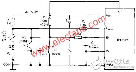
Active filters are various filters that contain active devices such as transistors, operational amplifiers. Compared with a passive filter that uses R, L, and C components alone, it can eliminate bulky inductor components and facilitate miniaturization and integration. Active filters are suitable for filtering at lower frequencies. A typical circuit for a second-order active bandpass filter is shown in the figure below.

6, isolation technology
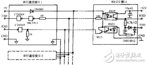
The so-called isolation technology refers to the technique of isolating the noise source from the signal line. In the microcontroller series, optocouplers are often used to isolate the sensor from the input channel, isolate the I/O interface, and isolate the internal circuitry. In addition, opto-isolation technology is also required when transmitting signals over long distances. A network communication interface circuit using photoelectric isolation technology is shown in the following figure. When isolating the transmitted analog signal, a linear optocoupler should be used with a current transfer ratio close to a constant.

In addition, transformer isolation, relay isolation, and frit isolation are often used in test systems.
7, resist interference on the transmission line
The transmission line should use twisted pair or coaxial cable shielding. Although the frequency band of the twisted pair is narrow, its wave impedance is high, and it is resistant to common mode interference. The electromagnetic inductance of each small loop on the twisted pair is applied. They can cancel each other out, and their distribution capacitance is large, which can achieve the effect of integrating capacitance, so it has a certain resistance to electromagnetic fields. Pay attention to the impedance matching problem when using long transmission lines. Otherwise, reflected waves will be generated on the transmission line, causing signal distortion.
8, choose the correct grounding point
Within the MCU measurement and control system, there are roughly six kinds of ground lines: signal line, analog ground, digital ground, power ground, AC ground and shield ground.
When designing the whole circuit, it should be determined according to the technical conditions and actual conditions whether it is floating or grounding. Which kind of grounding wire should be used, choose single point grounding or multi-point grounding.
9, the shielding of the sensor
When using an integrated temperature sensor in an industrial field, it is easy to introduce interference. To increase the signal to noise ratio, the sensor can be shielded. Some temperature sensors are packaged in a TO-52 metal case with a dedicated pin connector. When the ground is grounded during use, the casing can be shielded. For the integrated temperature sensor of the plastic package, if necessary, a thin copper tube can be used for external shielding, and the sensor is filled and sealed with epoxy resin, and the two are kept insulated. This fully sealed sensor is particularly suitable for measuring the temperature of liquids and vapors.
10, the shielding of plastic machine
At present, the plastic case made of ABS engineering reverse material is favored by people because of its beautiful appearance and light weight. In order to shield the chassis, a conductive film may be coated on the inner surface of the chassis by spraying, vacuum, or deposition. It is also possible to process the shielding layer by itself, stick a layer of aluminum foil on the inner surface of the chassis, and then communicate with the public ground.
11, the choice of components
In order to reduce the noise of components, metal film resistors and low noise active devices should be used as much as possible. In order to reduce temperature drift, all components are subjected to high and low temperature aging treatment. If necessary, the preamplifier and active filter should be equipped with a temperature compensation circuit. The integral capacitance of the A/D converter should be a polypropylene or polystyrene capacitor with low leakage and low dielectric loss factor. Both the ICL7650 precision op amp and the IC7660 DC/DC converter pump capacitors should be tantalum capacitors.
High-speed devices can be used without low-speed devices, and high-speed devices are only used in critical locations.
12, noise cancellation circuit
The bandgap reference is a high-stability voltage source that is used as a voltage reference and is currently used in digital instruments, smart instruments, and test systems. A 0.1UF noise canceling capacitor is connected in parallel with the reference voltage output to filter out high frequency noise.
The maximum value of the noise voltage that is allowed to be applied to the input when the output state of the circuit remains unchanged is called the voltage noise margin. The higher the noise tolerance, the device's anti-interference ability, should try to replace the TTL circuit with CMOS circuit. CMOS circuits have a noise margin of up to 40% of the supply voltage, while TTL circuits are only about 16% of the supply voltage.
13, power supply coupling capacitor
Many circuits in the MCU measurement and control system share a DC power supply. This requires that the power cord must not introduce interference between the circuits and that there should be no fluctuations in the DC power line when the load changes. But it's actually hard to do because of the internal impedance of the DC power supply, and there should be no fluctuations in the DC power line when the load changes. But it is actually very difficult to do because the internal impedance of the DC power supply and the AC impedance of the power supply lead cannot be zero. The decoupling capacitor can not only reduce the internal impedance of the DC power supply, but also avoid mutual interference between the circuits through the power line.
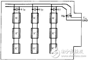
A large number of digital ICs are used in the MCU measurement and control system, and each digital IC itself is a pulse interference source, and they also interfere with each other through the power line. The solution is to connect a 10UF~100UF tantalum capacitor in parallel with the power supply terminal of the printed circuit board for power supply decoupling. At the same time, a high-frequency, low-distribution inductor ceramic capacitor is connected in parallel with the power supply input end of each chip. Generally take 0.1UF, when the frequency exceeds 15MHZ, it can take 0.01JF, the circuit is as shown. The pins of the decoupling capacitor should be as short as possible.

Transmission Line Construction unmanned aircraft systems
Transmission line dedicated unmanned aircraft the act of flying a strong and lightweight rope and attaching it to the towers, is typically performed via helicopters or by workers climbing the towers. Both these methods involve risk to both helicopter pilots and ground crews. The use of is eliminating the previously complex process consisting of several steps of reattaching the rope and decreasing the risk of injury for involved people.
This is a great proof of concept for unmanned aircraft because we proved that they can string both the outboard lines and the center line through the middle of the center phase of a tower. There are risks associated with both helicopter and tower climbing methods.
Fire Department Use Drone,Agriculture Drone Sprayer,Inspection Surveillance Mapping Drone,Cargo Quadcopter Drone
MARSHINE , https://www.puller-tensioner.com
