
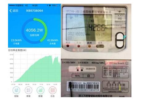
In fact, the power read from the inverter may not be the same as the power read from the meter. Under normal circumstances, there will inevitably be losses from the inverter to the meter. According to the law of conservation of energy, the amount of electricity produced by the energy meter is lower than that shown by the inverter. In practical applications, due to the measurement error of the inverter and the measurement error of the power, the power of the meter is higher or lower than the power displayed by the inverter. This is normal. This article first introduced the working principle of the inverter, and then answered the reason why the electricity generated by the inverter and the electricity meter are different, and gave a detailed description of the four cases. The specific follow Xiaobian together to find out.
How does the inverter work?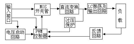
Input interface section:
The input section has three signals, a 12V DC input VIN, a working enable voltage ENB, and a Panel current control signal DIM. VIN is provided by the Adapter. The ENB voltage is provided by the MCU on the motherboard. The value is 0 or 3V. When ENB=0, the Inverter does not work, and when ENB=3V, the Inverter is in normal operation. The DIM voltage is provided by the motherboard. The change range is between 0 and 5V. Different DIM values ​​are fed back to the feedback end of the PWM controller. The current provided by the Inverter to the load will also be different. The smaller the DIM value is, the larger the output current of the Inverter will be.
Voltage start circuit:
When ENB is high, the output voltage is high to light the backlight of the Panel.
PWM controller:
It consists of the following functions: internal reference voltage, error amplifier, oscillator and PWM, overvoltage protection, undervoltage protection, short circuit protection, and output transistor.
DC conversion:
A voltage conversion circuit is composed of a MOS switch and an energy storage inductor. After the input pulse is amplified by the push-pull amplifier, the MOS transistor is driven to perform a switching action, so that the DC voltage charges and discharges the inductor, so that the other end of the inductor can obtain the AC voltage.
LC oscillation and output circuit:
Ensure that the lamp starts with the required voltage of 1600V, and reduce the voltage to 800V after the lamp starts.
Output voltage feedback:
When the load is working, the sampling voltage is fed back to stabilize the Inventer voltage output.
In fact, you can imagine it. All those electronic components need positive and negative electrodes, and resistors and inductors are generally not needed. Diodes are generally bad and may be broken down as long as the voltage is normal and there is no problem. The transistor will not turn on. If the voltage regulator is reversed, it will be damaged, but the general protection of some circuits is to use the diode's unidirectional conduction to protect. When it is a capacitor, there is a positive and negative capacitance in the capacitor which is the electrolytic capacitor. If the positive or negative connection is serious, the case will burst.
The main component diode. Switch tube oscillation transformer. sampling. Widen the tube. There is also the principle of the switch circuit with the resistance and capacitance of the tank circuit.
The selection of the main power components of the inverter is of vital importance. Currently used Darlington power transistors (BJT), power MOSFETs (MOSFETs), insulated gate transistors (IGBTs) and turn-off thyristors GTO), etc., are more commonly used in small-capacity low-voltage systems as MOSFETs because MOSFETs have lower on-state voltage drop and higher switching frequency, and IGBT modules are generally used in high-voltage large-capacity systems. The on-resistance of the MOSFET increases with the increase of the voltage, and the IGBT occupies a large advantage in the medium-capacity system. In the ultra-large-capacity (above 100KVA) system, the GTO is generally used as a power element.
Large items: FETs or IGBTs, transformers, capacitors, diodes, comparators, and masters like the 3525. There are rectification and filtering.
Power size and accuracy are related to the complexity of the circuit.
IGBT (Insulated Gate Bipolar Transistor) is a novel power semiconductor field controlled self-switching device that integrates the high-speed performance of power MOSFETs and the low resistance of bipolar devices. It has high input impedance, low voltage control power consumption, and simple control circuit. , high pressure resistance, high current withstand, etc., have been widely used in various power conversions. At the same time, major semiconductor manufacturers continue to develop IGBTs with high withstand voltage, high current, high speed, low saturation pressure drop, high reliability, and low-cost technologies. The following 1um production process is mainly adopted, and research and development have made some new developments.
1, the principle of power calculation
To understand the reasons for this, first of all we have to find out exactly how the electricity was calculated. To learn high school physics, you should know that the power calculation formula is:
W = UIT=I2RT
formula:
W---The amount of electricity generated by the photovoltaic system, the unit is KWH
U--- Mains voltage in V
I --- output current in A
T---The daily electricity consumption time, unit h
R---Output cable impedance in ohms
No matter what kind of equipment, the rules for calculating the power are the same. According to the data of three physical variables of voltage, current, and time, the power is calculated by different algorithms.
2. Inverter power calculation
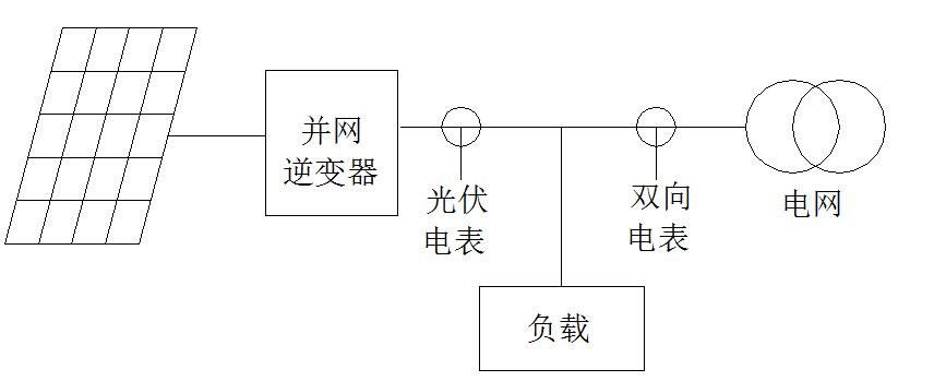
In addition to the DC-to-AC work of the inverter in the entire PV system, all the dynamic operation data of the power station is completed on the inverter side, and the power calculation is also part of it. The inverter collects voltage and current data through a built-in current sensor and a voltage sampling circuit. The software calculates the starting power and displays it on the inverter screen and monitoring platform.
The calculation of inverter power generation involves the detection of voltage and current. From the current sensor to the computing chip, there is a hardware sampling processing circuit, the accuracy of the current sensor is about ± 0.5%, plus the hardware sampling circuit and software calculations, the overall accuracy is about ± 1%.
3, electricity meter calculation
At present, there are many types of energy meter, but the principle of measuring power is essentially the same. Taking an electronic energy meter as an example, the current and voltage sensors of the circuit under test are converted, and the data is converted by the module converter and then input. The processor performs analysis and processing, and displays the forward and reverse active and reactive power measured by time-sharing.
Like the inverter, the meter's measurement is also erroneous. The single-phase or three-phase meter will have the accuracy grades of 0.2S, 0.5S, 1.0S, 2.0S, etc. on the nameplate, meaning that it is allowed to be within ±0.2%. Errors within ±0.5%, ±1.0%, and ±2.0%, and the current meter's accuracy level is 1.0S, so there is an error of ±1%.
4, case analysis
Knowing the basic measurement rules of electricity, the following is a practical example to establish a mathematical model to look at the difference between the inverter display power and the power meter display power under different conditions.
Case 1 : A 10KW photovoltaic power station in Henan Province, with three-phase 380V output connected to the grid, using a growatt 10000TL3-S model, the output side of the inverter using 6 square copper wire access, the output side of the inverter to the power meter distance It is 30 meters. One day's electricity generation is calculated according to the full load for 4 hours. The daily electricity generation amount is: 10KW*4h=40KWH
Cable loss calculation formula:
â–³W=I2RT (1)
R=ÏL/S (2)
The loss of the three output phase lines can be calculated as 0.16KWH using the formula and cable length and size
Case 1: Inverter current measurement accuracy is -1%, meter measurement error is 1%
Inverter detected output current:
I=15.2A*(1-1%)=15.05A
Inverter shows power generation W1=UIT=39.6 degrees
Electric meter shows power generation W2=40.2 degrees
Conclusion: W1 W2
Case 2 : Inverter current measurement accuracy is +1%, meter measurement error -1%
A similar calculation to case 1 yields:
Inverter shows power generation W1 = 40.4 degrees
Electric meter shows power generation W2=39.4 degrees
Conclusion: W1′′ W2
Case 3 : Inverter current measurement accuracy is -1%, meter measurement error -1%
A similar calculation to case 1 yields:
Inverter shows power generation W1=39.6 degrees
Electric meter shows power generation W2=39.4 degrees
Conclusion: W1′′ W2
Case 4: Inverter current measurement accuracy is +1%, meter measurement error is 1%
A similar calculation to case 1 yields:
Inverter shows power generation W1 = 40.2 degrees
Electric meter shows power generation W2=40.2 degrees
Conclusion: W1=W2
Zgar International (M) SDN BHD , https://www.szvape-pen.com