Several new terms and definitions have redefined new limits for LED lighting product design and testing.
Functional ground
Terminals that are not grounded for safety reasons. Note: In some cases, functional grounding must help to initiate and/or avoid radio interference.
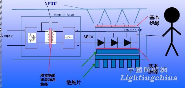
The functional grounding of the control unit is extremely connected and should be double or reinforced with live parts
* ELV (extra low voltage)
The voltage between conductors or between any conductor and ground does not exceed 50 V ac or 120 V dc without ripple. If one cable (pole) is insulated and the other is bare, the limit is 50 V ac or 120 V dc; if both cables (poles) are bare, the limit is 25V ac or 60 V dc
*SELV (Safety Extra Low Voltage)
It is an ELV and is isolated from the mains in the line, and its insulation is not lower than the insulation between the primary and secondary of the safety isolating transformer of IEC61558-2-6.
Notes: 1. A maximum voltage of less than 50 V ac rms or no ripple of 120 dc is specified in special requirements, especially when direct contact with conductive parts is permitted.
2. When the power source of the light source comes from a safety isolating transformer, the voltage limit should not be exceeded under any load between no-load and full load.
3. “No ripple†is a RMS ripple voltage not exceeding 10% dc. * The maximum peak value of a 120V rated ripple-free system does not exceed 140V.
* No more than 70V in a 60V rated ripple system.
* No more than 35V in the rated 30V ripple-free DC system.
main body
Used as a general item in the standard, it includes all accessible parts, shafts, handles, knobs, grippers, and the like, accessible metal fixing screws and metal foil covering the surface of the insulating material; excluding untouchable Metal parts.
New requirements for grounding terminals for stand-alone control units
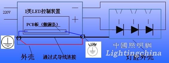
The ground terminal of the stand-alone control unit allows the grounding of the lamp cavity driven by the control device, but the conductors of the three cases between the ground terminal input and output connections should be subjected to the following tests:
(1) If the protective grounding path is provided via the printed circuit board printed line (blue), an alternating current of 25A is applied between each accessible metal member, and then: the grounding resistance does not exceed 0.5 Ω. (Shell--printing line--the same is true for the grounding terminal)
(2) If it is a loop or a through-wire connection (black path), it shall comply with IEC 60598-1, 5.3.1.1 and Chapter 7. Minimum wire diameter 1.5mm and grounding terminal/material/connection/fastening requirements , resistance ≤ 0.5 Ω
(3) If the grounding is connected through the outer casing (red path), the same as (2) is required.

If the internal grounding is provided by the printed circuit board, the following test shall be carried out on a stand-alone, integral or built-in control unit.
* Connect 25A AC current between the grounding terminal or grounding device connected to the printed circuit board of the printed circuit board and each easily accessible metal part for 1min.
* After cooling the control unit to room temperature, it should comply with IEC60598-1 7.2.3 (grounding resistance)
* Allows the built-in control unit to be grounded by mounting on the grounded metal of the luminaire
* Do not allow lamps or other devices to be grounded through built-in controls
Protection against electric shock (shock)
There should be no connection between the SELV output line and the main body or protective earth line except for Y1 or 2 Y2 capacitor bridges or 2 resistance bridges in accordance with 14.1 of IEC 60065. The output line is electrically isolated from ground by at least basic insulation. When only one output pole is touched, the output pole can be up to 50 V ac or 120 V dc because the voltage or contact current of the electrode does not exceed the following requirements.

