This article will introduce Xilinx's latest reference solution for crest factor reduction (CFR), also known as peak to cancel crest factor reduction (PC-CFR). This article will first review the purpose of using CFR technology, and then briefly review various CFR technologies, including performance comparisons between various solutions used in the multi-carrier TD-SCDMA standard. This article will also discuss FPGA resource requirements for implementing specific TD-SCDMA multi-carrier system configurations.
Amplitude factor and RF power amplifier efficiency
The power efficiency of radio frequency power amplifier (RFPA) plays a very important role in the design of cellular radio frequency base stations. Efficient RFPA solutions will reduce equipment investment (CAPEX) because smaller power amplifiers can be used for the same desired output power value or require less cooling infrastructure. On the other hand, because it consumes less power, it can also reduce operating expenses (OPEX).
The demand for higher efficiency of RF power amplifiers has evolved the base station architecture from a single carrier power amplifier output passive combination to an intermediate frequency carrier digital combination based on a multi-carrier power amplifier method. The latter method also allows the use of CFR technology and digital linearization technology including DPD.
However, a linear combination of carrier signals will have a high peak-to-average power ratio (PAPR). This applies not only to 3G CDMA carriers, but also to multi-carrier EDGE and GSM signals. Due to the linear combination of independent waveforms in the process of generating a single CDMA and OFDM carrier, even a single carrier CDMA or OFDM signal will show a high amplitude factor (CF).
When CF is used to measure PAPR, it can be defined and calculated by the following equation:

Where x is the true value of the up-converted bandpass signal.
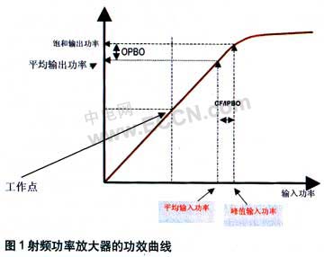
The high crest factor requires the commonly used class AB RFPA to operate at certain output back off levels (Output Back Off Level) to prevent high peak signals from driving the RFPA into the non-linear working area. First examine the relationship between CF and RFPA efficiency. The efficiency of RFPA is defined as the ratio of average output power to DC power at a certain operating point, which means that in order to achieve higher efficiency, the RFPA output should be driven close to the saturation point (non-linear effects will occur beyond the saturation point) . However, in actual operation, the output power should be backed up, not only to solve the CF problem of the input signal to RFPA, but also to solve other weak nonlinear problems in RFPA.
Figure 1 illustrates the relationship between input power back-off (IPBO) and output power back-off (OPBO). In order to achieve the desired OPBO level, the IPBO must be increased. Because the operating point remains the same, the denominator in the equation will remain the same, but the numerator will decrease, and a larger OPBO will cause a decrease in efficiency.
The efficiency of typical RFPA of different types of amplifiers with strong transconductance nonlinearity is described in Figure 2, and the OPBO function is expressed in dB. For Class AB RFPA with 12dB OPBO, as the back-off increases, the efficiency decreases from 70% to about 10%.
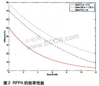
Considering the high CF of the signal, there are two ways to solve the problem of reduced efficiency caused by the increase of OPBO. One is to use an effective crest factor reduction (CFR) scheme to reduce the PAPR of multi-carrier input signals, and digital predistortion (DPD) to extend the linear operating range of RFPA. By reducing the PAPR of the RFPA combined input signal, the IPBO can be reduced, making the OPBO lower, thereby achieving efficiency improvements.
Compared with the case of not using CFR to achieve an 8% efficiency increase, a typical efficiency increase of approximately 16% can be achieved using the CFR scheme. In the following, we will review the commonly used technologies and discuss in detail the peak-to-crest factor reduction (PC-CFR) scheme in terms of performance and resource utilization of TD-SCDMA multi-carrier applications.
Various CFR technologies
Currently, crest factor reduction schemes cover coding options, I & Q or baseband polarity limiting, peak windowing CFR (PW-CFR), noise shaping CFR (NS-CFR), and pulse injection CFR (PI-CFR).
Xilinx recently proposed a technology called PC-CFR, which has been proven to perform better. At the same time, among other advantages, it can consume less resources because it reduces the computational burden by itself.
Before discussing PC-CFR in detail, we will first briefly review the three common technologies mentioned above.
PW-CFR
PW-CFR is an extension of conventional limiting technology, and PAPR can be reduced by applying the time-domain scaling of the amplitude-limited signal. The equation used for conventional clipping is as follows: y [n] = c (n) · x (n) c (n) is defined by the following equation:
Where A is the maximum allowable amplitude limit signal. The idea is to use a smooth function b (n) instead of c (n) and use a suitable window to limit the spectrum spread of the limited signal. The block diagram of PW-CFR is shown in Figure 3.
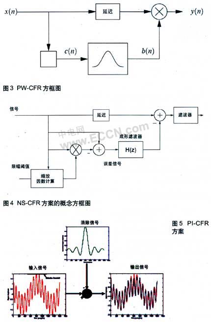
The performance of the signal y (n) adjacent channel leakage power ratio (ACLR) and error vector magnitude (EVM) processed by PW-CFR depends on the window used and the length of the window. The window length provides a compromise between ACLR and EVM performance. Longer windows can provide better ALCR, which is at the expense of EVM performance degradation.
NS-CFR
This solution was first provided by Xilinx to the WCDMA digital front end and then WiMAX. By eliminating all sampling points that exceed a certain clipping threshold, NS-CFR can reduce CF.
Figure 4 depicts the block diagram of the NS-CFR system. Traditional polarity limiting is used to cut signal peaks above a certain threshold. The limiting signal is then shaped by noise to ensure that the noise caused by the limiting measures falls within the signal band.
The noise-shaped clipping signal is then eliminated from the original signal, thereby reducing PAPR. The above-mentioned processing may cause the peak value to rise again, and this scheme can be adopted repeatedly in the subsequent stage to mitigate the peak value from rising again.
Compared with PW-CFR, NS-CFR scheme can provide better performance.
PI-CFR
The simplified version of the PI-CFR scheme is shown in Figure 5. This technique is usually equipped with last-stage digital clipping.
In essence, the PI-CFR scheme detects the peak of the introduced high PAPR signal at a small sampling rate, and for each peak that exceeds the limiting threshold, a corresponding "whole" signal with the same amplitude will be generated with the opposite phase . The resulting signal is then used to eliminate the detected peak signal, as shown in the block diagram of FIG.
A typical PI-CFR system contains a large number of detection and elimination (PDC), and a limited number of pulse generators. In this process, the peak value may rise again due to the simultaneous use of multiple PDC stages.
PC-CFR
PC-CFR technology uses a technology similar to NS-CFR to shrink the CF. However, unlike the NS-CFR described above, the signal regenerated by spectrum shaping in the PC-CFR scheme is based on the peak sampling point, and this signal is used to cut the original peak signal that exceeds the threshold after proper delay processing. However, for NS-CFR, all the noise samples with limited amplitude are filtered out and used to subtract the corresponding original delayed peak signal.
As a simplified method using only peak sampling points for reduction, it has less distortion and requires less computational burden. In each PC-CFR stage, it contains up to 4 elimination pulse generators (CPG) and has a complex peak scaling function. Another advantage of the PC-CFR scheme is its flexibility, that is, it can support multiple air interface standards by appropriately changing filters on the same system.
Figure 6 depicts a complementary cumulative distribution function (CCDF) graph of 15MHz bandwidth, 1E-4 with 3dB gain, CFR input and output between 7% EVM operating point and 6 non-adjacent TD-SCDMA carriers. This simulation is based on an output sampling rate of 76.8 MSPS. Figure 7 describes the power spectral density (PSD) performance after adding a Spectrum Emission Mask for a similar configuration.
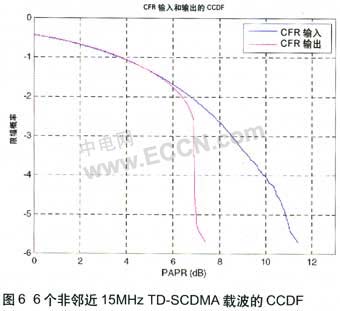
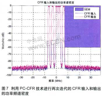
Figure 8 shows the performance comparison between PC-CFR, NS-CFR and PW-CFR. Note that PC-CFR provides the best performance for different EVM values, and if you exceed two PC-CFR iterations, the performance will hardly increase.
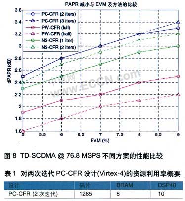
Table 1 shows the FPGA resources required for two PC-CFR iterations.
For example, for a 10MHz 6-carrier 3-antenna (6C3A) TD-SCDMA 76.8MSPS digital front end, each antenna requires two iterations of the PC-CFR module. Table 2 shows the resource utilization requirements. This configuration is applicable to base stations and remote radio frequency units (RRU).
According to the data in Table 2, the designer can build a complete 6C6A digital front-end solution using two V4SX35 FPGAs. This scheme uses CFR measures to provide more efficient RFPA operation. This is critical, especially in RRU working environments that require conduction cooling.

Conclusion
As can be seen from this article, the PC-CFR scheme is clearly the winner because it can provide better performance and lower FPGA resource utilization than other known schemes. These advantages, combined with the availability of compatible TD-SCDMA DFE reference designs, allow infrastructure equipment developers to shorten time to market and have a greater chance of success.
We supplier the largest selection of disposable vape from China. and deliver to the destination just cost 7-15days. Over 1000 products available now!High quality 100% Original supply, wholesale price is reasonable.
In stock Disposable vape deliver in the same day,pre sale vapes will be delivered within 7 days.
Disposable vapes are a cheap and simple way to try vaping for the first time.It easy to carry and vaping.
A wide range of products, including Vape 600 Puffs , Vape 800 Puffs ,vape1500 puffs, Vape 2000 Puffs ,Vape 3000 Puffs,Vape 5000 Puffs, Vape 8000 Puffs ,Big Smoke,Rechargeable Vape,Mesh Coil vape, Flash Vape ;

Disposable vapes are immensely popular and convenient e-cigarettes that come ready to vape out of the packaging and are disposed of once the device/kits runs out,
90% of the world's e-cigarettes are produced in China, so the price and quality are superior. If you are in the e-cigarette business, you must not miss it. Our professional service and high-quality products will surely satisfy you.
Disposable Vape,Disposable E-Cigarette,Vape Pod,Mini E Cigarette
TSVAPE Wholesale/OEM/ODM , https://www.tsvaping.com
