SERDES (serial-to-transceiver unit) hard cores are integrated in high-end FPGAs of current mainstream manufacturers. For example, Altera's Stratix IV GX device family integrates SERDES single channel to support data rates from 600 Mbit/s to 8.5 Gbit/s, while Stratix The IV series device family also integrates high-speed differential signal interfaces from 150Mbit/s to 1.6Mbit/s and enhances its Dynamic Phase Alignment (DPA) feature. Xilinx's Virtex II Pro's embedded SERDES single channel supports 622Mbit. /s to 3.125Mbit/s data rate, while Virtex II Pro X embedded SERDES single channel supports 2.488Gbit/s to 10.3125Gbit/s data rate; Lattice's high-end SC series FPGA embedded SERDES single channel supports 622Mbit /s to 3.4Gbit/s data rate, and its various programmable system-on-chip FPSC (FPSC, Field Programmable System Chip) embedded different performance SERDES single channel supports data rates from 400Mbit/s to 10.709Gbit/s .
Embedding a hard core such as SERDES in an FPGA can greatly expand the data throughput of the FPGA, save power, improve performance, and make the FPGA play an increasingly important role in high-speed system design.
Based on the basic concepts of SERDES, the SERDES and DPA structures of Stratix IV GX are discussed. By introducing typical high-speed system design examples and high-speed PGB design considerations, readers will enter the world of high-speed system design.
The basic concept of SERDES
Here we will introduce the basic concepts of SERDES and introduce the proper terms related to SERDES: Eye-diagram, eye diagram template, jitter, tolerance, power consumption, pre-emphasis ( Pre-emphasis, Equalization, 8B/10B encoding, etc.
SERDES concept
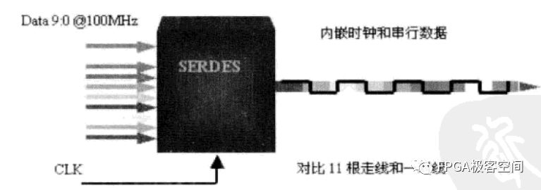
SERDES is the abbreviation of SERializer and DESerializer, which is a serial transceiver. As the name implies, it consists of two parts: the originator is a serial transmission unit SERializer, which uses a high-speed clock to modulate the encoded data stream; the terminal is a serial receiving unit DESERializer whose main function is to recover the clock signal from the data stream and demodulate it. Data, according to its function, the receiving unit also has a name called CDR (Clock and Data Recovery) or CRU (Clock Recovery Unit). As shown in the figure, a schematic diagram of serial transmission and deserial reception of 10 data lines is shown. Ten 100 MHz signal lines are input into the SERDES device to generate a serial code stream, and the clock is also modulated into the code stream, which in turn recovers parallelism. Data and clock. The application of SERDES technology solves the bottleneck of high-speed system data transmission (especially the backplane transmission application), saves the board area and improves the stability of the system, and is a strong support for high-speed system design.


10:1 SERDES function diagram
Eye diagram and eye diagram template
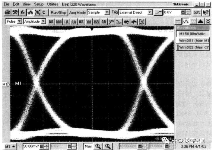
The two most important parameter indicators of SERDES are the transmission rate and the transmission length, which is the transmission rate at which the transmission rate can meet the bit error rate. The evaluation method of the image is to use the eye diagram. The height and width of the eye diagram reflect the transmission quality of the signal. The figure shows an eye diagram of the Altera Stratix IV GX device.

AlteraStratix IV GX device eye diagram example
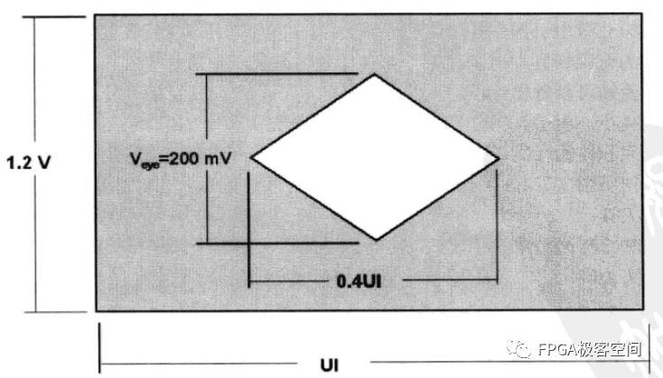
The eye diagram template is a reference frame for comparing the quality of the eye diagram. There are two common eye template templates: a diamond template and a hexagonal template. As shown in the figure, the diamond eye diagram is shown.

Diamond eye diagram
Among them, the common axis is the height of the eye diagram, the unit is Mv, which is used to indicate the amplitude of the correctly received differential signal, and is directly related to the level requirement of the signal that can be correctly recovered at the receiving end; the horizontal axis is the width of the eye diagram, and the unit is UI. Or ps, which is used to indicate the reception time without inter-code interference, and is directly related to the ability of the receiving end to distinguish two adjacent symbols. UI, the abbreviation of Unit Interval, that is, the corresponding time of the 1-bit data period, for example, the 1UI of 1Gbit/s eye diagram is 1 ns. The standard for evaluating eye diagrams is that the eye is opened to a greater extent and the eyeliner is clear. The eyeliner clearly indicates that the whole system has small jitter and high accuracy; the eye diagram has a large degree of opening, indicating that the received signal has a large amplitude and small time jitter, so that the amplitude and time tolerance of the receiving end is lower, and the signal is correctly recovered. The probability is even higher.
In the e-bike market where innovative, minimalistic designs are talk of the day, we see that manufacturers are constantly looking for smart electrical wiring systems and reliable connections to support these developments. With years of experience with our e-bike customers, we have already worked successfully around themes like the integration of brake & signal, battery and number plate lighting, high power electrical connection.
Related products:bike wire assembly, ebikes connector,e-bike cable assemblies, waterproof e-bike cable, waterproof e-bike connector
bike wire assembly, ebikes connector,e-bike cable assemblies, waterproof e-bike cable, waterproof e-bike connector
ETOP WIREHARNESS LIMITED , https://www.etopwireharness.com
