For the data communication between the 8-core DSP TMS320C6678 and external devices, the integrated chip Gigabit Ethernet switching subsystem is taken as the core, and the chip 88E1111 is selected as the PHY device, and the hardware circuit of the Gigabit Ethernet communication interface is designed. In the embedded operating system SYS/BIOS and network development environment NDK, the programming of the underlying Ethernet driver and TCP/IP protocol is completed. The Ethernet communication test with the host computer through the DSP proves the correctness and practicability of the hardware and software of the Ethernet interface circuit.
As DSP processors become more widely used in modern industries, DSP functions not only require fast arithmetic processing, but also real-time data exchange with other processors or devices to achieve resource sharing. Therefore, for a variety of equipment needs, the choice of a stable, fast and efficient interface is a key component in today's digital signal processing system design.
TI's 8-core processor TMS320C6678 (hereafter referred to as C6678) provides a wealth of on-chip interface resources for communication between the processor and peripherals. These interfaces can be used for communication between DSP and peripherals, but flexibility Differences, using the SGMII interface to achieve Gigabit Ethernet communication, can make the communication interface general, can be applied to a large number of device connections. This paper designs and implements Gigabit Ethernet communication for the chip characteristics of C6678 and the interface resources. It mainly designs the Ethernet interface circuit, the network underlying hardware driver, the TCP/IP protocol user program, and completes the Ethernet with the host computer. Communication test realizes high-speed and efficient network transmission of digital signals.
1 C6678 Ethernet Switching SubsystemThe C6678 is an 8-core high-performance, fixed-point/floating point processor based on the KeyStone I architecture with a single core operating at up to 1.25 GHz. The Ethernet switching subsystem of the C6678 includes two Ethernet Media Access Controllers (EMACs), two SGMIIs, one Management Data Input Output (MDIO), and a 3-Port Ethernet Switching Module. And the network configuration bus, its network switching subsystem is shown in Figure 1.
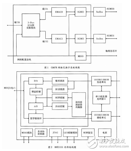
The function of EMAC is to convert the internal signal of the switching subsystem into GMII signal to the SGMII module; the MDIO control physical layer chip performs control input and output on the multi-data stream.
2 PHY chip 88E1111This paper chooses C6678 as the main chip. Since the G6 network switching subsystem of C6678 only supports SGMII interface, this paper selects the physical chip 88E1111 which has better compatibility with the network data transmission of SGMII interface. The internal structure of 88E1111 chip is shown in Figure 2. Show.
The media interface of the 88E1111 has a copper media interface and a fiber interface. The copper media interface is MDI[3:0], and the operating mode is selected by setting HWCFG_MODE[3:0]. The 88E1111 integrated MDIO module is connected to the MDIO interface of the EMAC, which can facilitate the network control terminal to read the physical chip status register to achieve real-time monitoring.
3 hardware interface designThe task of this paper is based on the interface design of the C6678 on-chip Ethernet switching subsystem and the off-chip PHY chip 88E1111 and its peripheral circuits. Mainly include: C6678 and 88E1111 chip connection, 88E1111 chip configuration and 88E1111 chip and network media connection.
3.1 C6678 and 88E1111 chip connection
The interface circuit of C6678 and PHY chip 88E1111 is shown as in Fig. 3. The 88E1111 operates in the SGMII interface mode and does not require the TXCLK clock input. It helps reduce the number of traces on the board and also reduces noise.
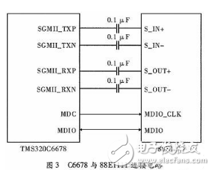
The main interface signals include clock and data signals as follows:
MDIO_CLK: Manages the data clock. This clock signal is provided by the MD6 module on the C6678 chip, which is controlled by configuring the CLKDIV bit in the MDIO control register, CONTROL.
SGMII_TXP and SGMII_TXN: Serial transmit differential data lines. Connect the internal SerDes of the DSP and the S_IN pin of the physical chip. The SerDes of the DSP sends serial data to the physical layer through the pin, and the data includes the transmit data clock signal.
SGMII_RXP and SGMII_RXN: Serial receive differential data lines. Connect the internal SerDes of the DSP and the S_OUT pin of the physical chip. The physical layer chip transmits data to the SerDes of the DSP through the interface, and the data includes the data receiving clock signal.
MDIO: Manage data I/O. Up to 32 PHY devices can be connected to the EMAC of the DSP, and all PHY devices can be enumerated, and the PHY device status register can be read to monitor the connection status of the PHY. The data frame structure conforms to the 802.3 standard and includes read and write instructions, PHY addresses, register addresses, and data.
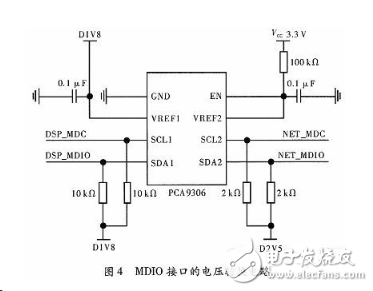
Because the integrated MDIO on the 88E1111 is connected to the C6678 integrated MDIO module, the voltage is different. The former voltage is 2.5 V and the latter voltage is 1.8 V. Therefore, a voltage converter should be added between the two. This article uses a PCA9306 to achieve level shifting between 2.5 V and 1.8 V. The connection circuit is shown in Figure 4.
3.2 88E1111 chip configuration
The 88E1111 is connected to the MDIO module of the C6678. The MDIO can identify up to 32 physical chips. It needs to be configured before using the physical chip. The configuration content mainly includes the address and mode of the chip. Configure the CONFTG[6:0] pin definition to query the literature. The hardware circuit configured in this paper is shown in Figure 5. In Figure 5, the resistor can be omitted. For the convenience of testing, add a 0 Ω resistor.

After the hardware configuration of 88E1111 is completed, the system will be fixed as an interface mode. According to the definition of the document, the address of the physical chip is: PHY_ADDRESS=0'b00001, and the chip mode is: SGMII mode without auto-negotiation with clock.
3.3 88E1111 chip and RJ45 connection
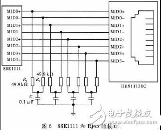
The 88E1111 and the network medium cannot be directly connected. Because the transmission speed is in the gigabit class, it is more necessary to design a suitable network isolation transformer to reduce transmission loss, echo and crosstalk. This article selects the Gigabit Ethernet port socket HR911130C, which has its own transformer circuit. It only needs to connect the filter network externally to realize the stable transmission of the network signal, as shown in Figure 6. The 88E1111 and HR9111130C use differential connections, which require strict equal lengths in PCB layout, and generally require an impedance matching network, such as R1 and C1 in Figure 6.
TI has released a Network Development Kit (NDK) for network development, which can transfer the configuration operations of multiple modules to the NDK network framework. At the same time, data subcontracting and parsing do not require too much consideration by programmers, which accelerates network development. process. The NDK is built on top of the real-time operating system SYS/BIOS. The NDK interacts with the BIOS through the OS abstraction layer. The BIOS cfg configuration file can visually view the NDK modules.
This paper designs an Ethernet communication program based on the multi-core DSP real-time operating system SYS/BIOS. The operating system can provide more integrated modules, which is convenient for users to write programs, and also has hardware and software interrupt management, multi-tasking synchronization mechanism, multi-core communication mechanism and memory management mechanism, etc., which can provide modularization for users to perform multi-thread multi-task development. s frame. The overall structure of the Ethernet communication interface software is shown in Figure 7.

SYS/BIOS provides an integrated development environment for the entire software. It not only has a multi-threaded preemption mechanism suitable for real-time systems, but also adds the required package libraries, making it easier to call library functions when writing programs. NDK is a DSP network application development integration tool, in which stack.lib gives a package library from the top-level socket to the underlying PPP on the TCP/IP protocol stack; nettool.lib provides socket sockets for network applications. The package library of the development tools; os.lib provides a package library for system coordination between SYS/BIOS and the network programming suite; hal.lib provides a package library for the interface between the peripheral device and the network protocol stack; netctrl.lib provides the DSP The overall control of network programming can be used to configure the underlying drivers and protocols.
The DSP on-chip system software is divided into three parts: SYS/BIOS platform and NDK TCP/IP protocol stack establishment and configuration; user program; compiling the underlying driver.
4.1 Implementation of the underlying hardware driver
The basic structure of the NDK is shown in Figure 7. It can be seen that the NDK development kit is closely related to the user program, the SYS/BIOS operating system, and the underlying hardware. The network control layer and operating system interface layer of the NDK are connected to the SYS/BIOS system. The hardware driver layer of the NDK is used to control the configuration of the underlying hardware driver. These operations and configurations can find corresponding driver functions in the network tool library. The implementation can be called directly by the user application.
These features mainly include:
(1) The underlying hardware driver includes: initialization of MDIO module and EMAC module; PHY chip search configuration and status monitoring; EMAC/MDIO interrupt enable. (2) The establishment of the TCP/IP protocol stack, configuring the size of the receiving and transmitting buffer area, and completing the task of transmitting and receiving Ethernet data. (3) Using the MDIO module, the PHY status register read by the MDIO is used to monitor its connection status, identify a status change event that may be an interrupt generated by the CPU, and feed back information. (4) Turn off the driver, reset the previous operations on the registers, and reclaim the occupied resources.
As shown in Figure 7, the hardware driver is included in the hardware driver layer hal.lib, and the user needs to modify the driver function according to the system. The C6000 series NDK API encapsulates many fixed driver functions and has specific functions. For example, _llPacketSerivceCheck() is used to detect the structure of Ethernet packets and feed back the detected structure information to the protocol stack for analysis and processing. The specific driver needs to be designed according to the configuration of the hardware system. In the C6678, the higher-level system-on-chip can directly query the registers of the network communication module, and the underlying hardware can be completed, so that the underlying hardware can be effectively Run.
4.2 DSP-side network application
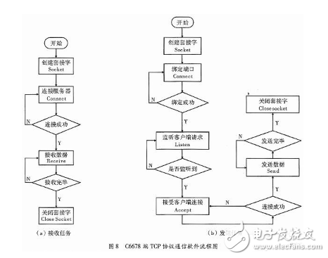
DSP software design is based on SYS/BIOS real-time multitasking operating system and C language, using Socket socket to create TCP/IP client (Client) and server (Server), Client is responsible for establishing connection with external device server and receiving The data packet, Server is used to send the processed data packet to the PC. The process of receiving tasks and sending tasks is shown in Figure 8. Two synchronous thread tasks, namely data receiving and sending tasks, are established in the kernel Core0 of C6678, which are used to receive the data sent by the TCP server and send the processed data to the PC host computer for processing, storage and display.
4.3 PC test program
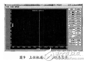
The host computer test program is based on VC++ MFC interface design, using socket Socket for network programming. Two synchronization threads need to be designed in the program to realize real-time data reception and dynamic display. The hull structure stress data is sent by the TCP server, and is received, processed, and transmitted by the DSP, and finally sent to the PC host computer for dynamic data display. The result is shown in FIG. 9.
This paper takes the 8-core processor C6678 as the core, and studies the interface hardware of the on-chip integrated Ethernet switching subsystem. According to the characteristics of the interface, the interface connection including the Ethernet switching subsystem and the physical chip, the physical chip and the network medium interface are designed. Connected hardware system, and completed the Gigabit Ethernet driver, and finally realized the multi-core DSP C6678 and the host computer for Gigabit Ethernet communication. Through network communication test with the host computer, the result shows that the Ethernet data communication interface can perform network data transmission in real time and efficiently.
ZGARVAPE
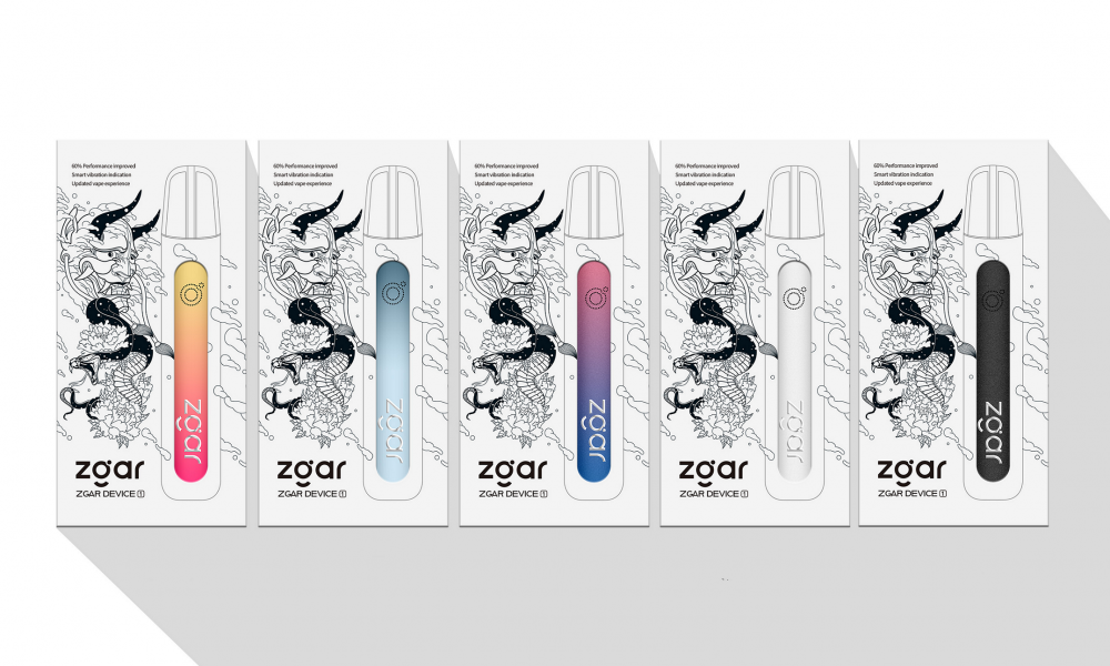
Zgar 2021's latest electronic cigarette Aurora series uses high-tech temperature control, food grade disposable pod device and high-quality material.Compared with the old model, The smoke of the Aurora series is more delicate and the taste is more realistic ,bigger battery capacity and longer battery life. And it's smaller and more exquisite. A new design of gradient our disposable vape is impressive. We equipped with breathing lights in the vape pen and pod, you will become the most eye-catching person in the party with our atomizer device vape.
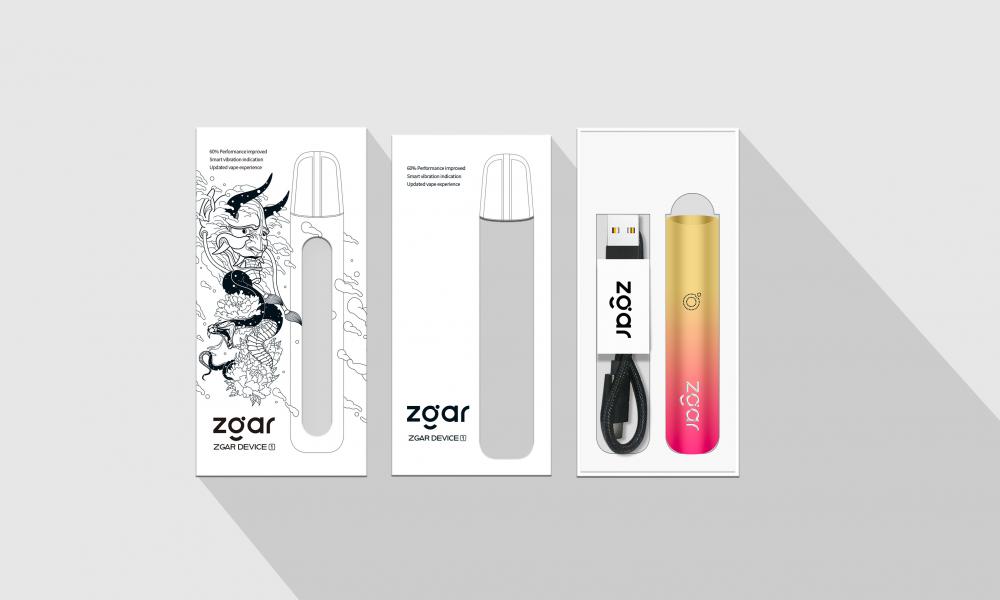
The 2021 Aurora series has upgraded the magnetic suction connection, plug and use. We also upgrade to type-C interface for charging faster. We have developed various flavors for Aurora series, Aurora E-cigarette Cartridge is loved by the majority of consumers for its gorgeous and changeable color changes, especially at night or in the dark. Up to 10 flavors provide consumers with more choices. What's more, a set of talking packaging is specially designed for it, which makes it more interesting in all kinds of scenes. Our vape pen and pod are matched with all the brands on the market. You can use other brand's vape pen with our vape pod. Aurora series, the first choice for professional users!
We offer low price, high quality Disposable E-Cigarette Vape Pen,Electronic Cigarettes Empty Vape Pen, E-cigarette Cartridge,Disposable Vape,E-cigarette Accessories,Disposable Vape Pen,Disposable Pod device,Vape Pods OEM vape pen,OEM electronic cigarette OEM e-cigarette OEM e-cig to all over the world.



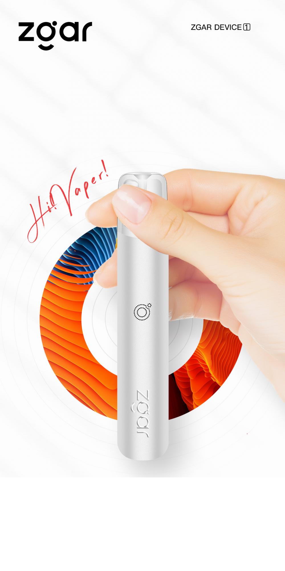
E-Cigarette Vape Pen,Disposable Device Vape,Vape Pen Atomizer,Latest Disposable E-Cigarette OEM vape pen,OEM electronic cigarette
Shenzhen WeiKa Technology Co.,Ltd. , https://www.zgarpods.com
