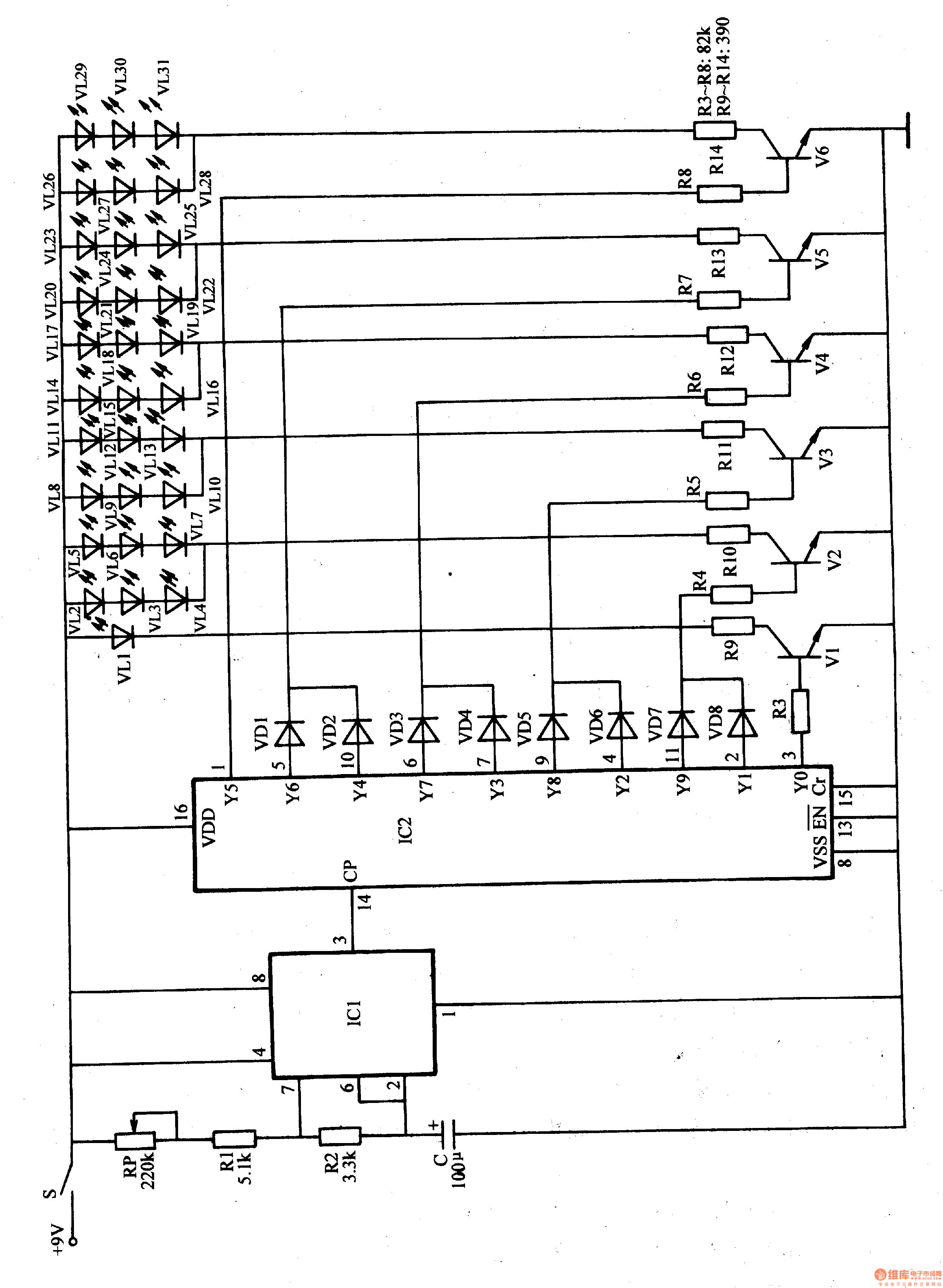
The multivibrator circuit is composed of a potentiometer RP, resistors R1, R2, a capacitor C, and a time base integrated circuit IC1.
The LED drive control circuit is composed of a time base integrated circuit IC2, a transistor Vl-V6, a diode VDl-VD8, a resistor R3-R14 and a light emitting diode VLl-VL3l.
After the power switch S is turned on, the multivibrator oscillates to provide a count pulse signal for IC2. Under the action of the counting pulse, IC2 outputs the high level in turn in turn, and the VLl-VL31 circulates through VDl-VD8, R3-R14 and Vl-V6.
When the YO terminal of IC2 outputs a high level, Vl is turned on, and VLl is lit.
When the Y1 terminal and the Y9 terminal of IC2 output a high level, V2 is turned on, and VL2-VL7 is lit.
When the Y2 terminal and the Y8 terminal of IC2 output a high level, V3 is turned on, and VL8-VLl3 is lit.
When the W terminal and the Y6 terminal of lC2 output a high level, V5 is turned on, and VL2O-VL25 is lit.
When the Y5 terminal of IC2 outputs a high level, V6 is turned on, and VL26-VL31 is lit.
As a result of this cycle, each LED light-emitting diode flashes.
Adjusting the resistance of the RP can change the blinking frequency of the LED.
Component selection
Rl-R14 uses 1/4W metal film resistor or carbon film resistor.
The RP uses a solid variable resistor.
C selects an aluminum electrolytic capacitor with a withstand voltage of 16V.
VDl-VD8 selects 1N4148 type silicon switch diode for use.
VLl-VL31 selects high brightness LEDs of d3mm or φ5mm.
Vl-V6 selects S805O or C8050 silicon NPN transistor.
ICl selects NE555 type time base integrated circuit; IC2 selects CD4017 or CC4017 type decimal counting/pulse distributor integrated circuit.
S uses a single-pole toggle switch.
KNBL1-32 Residual Current Circuit Breaker With Over Load Protection
KNBL1-32 TWO FUNCTION : MCB AND RCCB FUNCTIONS
leakage breaker is suitable for the leakage protection of the line of AC 50/60Hz, rated voltage single phase 240V, rated current up to 63A. When there is human electricity shock or if the leakage current of the line exceeds the prescribed value, it will automatically cut off the power within 0.1s to protect human safety and prevent the accident due to the current leakage.
leakage breaker can protect against overload and short-circuit. It can be used to protect the line from being overloaded and short-circuited as wellas infrequent changeover of the line in normal situation. It complies with standard of IEC/EN61009-1 and GB16917.1.
KNBL1-32 Residual Current Circuit Breaker,Residual Current Circuit Breaker with Over Load Protection 1p,Residual Current Circuit Breaker with Over Load Protection 2p
Wenzhou Korlen Electric Appliances Co., Ltd. , https://www.zjaccontactor.com
