
In order to form a unified standard in the industry, the MIPI Alliance initiated the MIPI (Mobile Industry Processor Interface) as an open standard for mobile application processors. So how to analyze the display module interface protocol MIPI-DSI in MIPI?
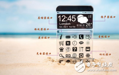
MIPI is an alliance established in 2003 by ARM, Nokia, ST, IT and other companies to standardize the internal interfaces of mobile phones such as storage interfaces, display interfaces, RF/baseband interfaces, etc., to reduce compatibility issues and simplify design.
The MIPI Alliance has different working groups that define a series of internal phone interface standards, such as camera interface CSI, display interface DSI, and radio interface DigRF. The advantage of the unified interface standard is that mobile phone manufacturers can flexibly select different chips and modules from the market according to their needs, and facilitate the design of appearance and function.

Figure 1 MIPI Alliance
The MIPI structure shown in Figure 2 below is divided into physical layer, protocol layer and application layer. At present, the more mature MIPI applications include camera CSI interface, display DSI interface and DigRF interface between baseband and radio, while other specifications such as UFS and LLI are being gradually developed and improved.
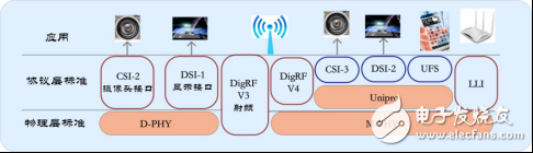
Figure 2 MIPI interface structure
2, MIPI-DSIMIPI-DSI belongs to the MIPI sub-protocol and is the specification standard for the display module interface developed by the Display working group. MIPI-DSI uses D-PHY as the physical layer transport.
The D-PHY uses a pair of source-synchronized differential clocks and 1 to 4 pairs of differential data lines for data transmission. The data transmission adopts the DDR mode, that is, data transmission is performed on the upper and lower edges of the clock.
(1) D-PHY transmission status: low power LP and high speed HS.
LP (single signal 0V~1.2V): Low power mode, 10Mbps transmission speed, asynchronous transmission, mainly used to transmit control commands.
HS (differential signal 100mv~300mv): High-speed mode, 80M~1Gbps transmission speed, synchronous transmission, used to transmit high-speed image data.
The HS differential and LP single signals are shown in Figure 3.
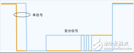
Figure 3 Single-ended and differential signals
(2) Three modes of D-PHY: Control Mode, Escape Mode, and HS Mode
The first two modes belong to the two modes in the LP state, the high-speed mode belongs to the HS state, and the Escape Mode is defined as a special operation mode in the LP state.
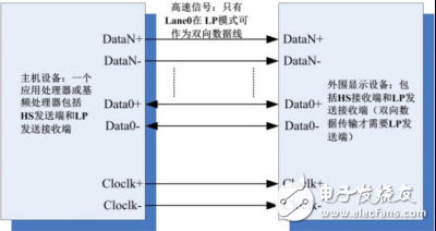
Figure 4 MIPI DSI application
MIPI-DSI uses single-ended and differential signal lines for data transmission, single-ended data transmission in LP mode, differential data transmission in HS mode, and configuration using Data0+/Data0-data Lanes that can be transmitted in both directions.
3. MIPI-DSI data transmission formatThe data transmission format of MIPI-DSI is transmitted in the basic unit of data packets, and the types of data packets are divided into short data packets and long data packets.
(1), short data packet: 4 bytes (fixed length) is mainly used to transfer commands, read and write registers;
Packet header:
· Data Identifier (DI)*1byte: Contains virtual data channel [7:6] and data type [5:0].
· Packet *2 byte: The data to be transferred, the length is fixed by two bytes.
· Error Correction Code (ECC)*1byte: A bit error can be corrected.
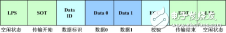
Figure 5 short packet structure
(2), long data packet: 6~65541 bytes (dynamic length) is mainly used to transmit a large amount of image data or partial control commands.
Packet header (4 bytes):
· Data Identifier (DI)*1byte: Contains virtual data channel [7:6] and data type [5:0].
· Bytes (WC)*2 byte: The data to be transferred, the length is fixed by two bytes.
· Error Correction Code (ECC)*1byte: A bit error can be corrected.
· Effective transfer of data (6~65541 bytes): Maximum byte = 2^16.
· Packet footer (2 byte): checksum.
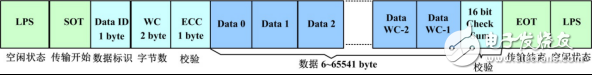
Figure 6 Long packet structure
4, example application and analysis(1) Field simulation MIPI-DSI protocol, using the data mining oscilloscope ZDS4054 Plus, which is equipped with the MIPI-DSI protocol low-speed LP mode decoding function free of charge. The specific operation is shown in Figure 7.
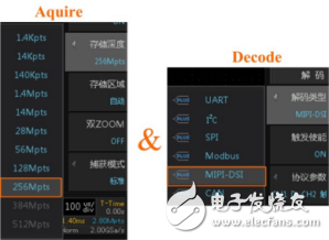
Figure 7 decoding step
(2) The ZDS4054 Plus comes standard with a storage depth of 512 Mpts and can decode all memory data. The MIPI-DSI protocol decoding interface is shown in Figure 8. The specific decoding content can be viewed through the event table, or the content in the event table can be exported by exporting the report format.

Figure 8 decoding interface
(3) When performing data anomaly analysis on long-term monitoring data, you can use the dual ZOOM multi-window display function in the zoom mode of the oscilloscope to perform multi-window abnormality monitoring and analysis on the signal, which can be used for a certain data frame or one. The data points are analyzed, and the details of the enlarged data are viewed to find the abnormality, as shown in Figure 9 below.
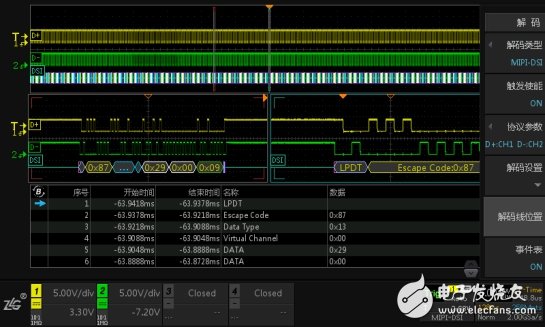
Figure 9 details analysis
As a Professional manufacturer of stage lights, our products base on High Quanlity Standard and competitive prices.
Moving head Beam Lights, wash zoom lights, LED Par Lights, COB matrix light, laser lights and fog machines, professional solution for decerating stage effects.
Stage lighting series products can be used in various large and small concerts, bars, restaurants, clubs, etc. Program them to make good effects for any stage by using DMX Controller. We also provide free solution for your to fit well to the plan.

Stage Light,Led Stage Lights,Stage Lighting,Stage Lighting Systems
Guangzhou Cheng Wen Photoelectric Technology Co., Ltd. , https://www.cwdisplay.com