
1. Design of flyback isolated power supply based on SE8510
Figure 1 is a schematic diagram of the SE8510 flyback isolated power system. The SE8510 is an off-line isolated primary-side control flyback LED driver control IC. The SE8510 uses a rugged high-voltage isolation process capable of withstanding an input voltage of up to 450 V. -450V wide input voltage range. Therefore, the SE8510 can be directly driven by the main line input voltage, simplifying the transformer design process. With accurate LED adjustment function, PWM adjustment control, open short circuit protection, over temperature protection and other functions. Making the overall application design easier than ever.
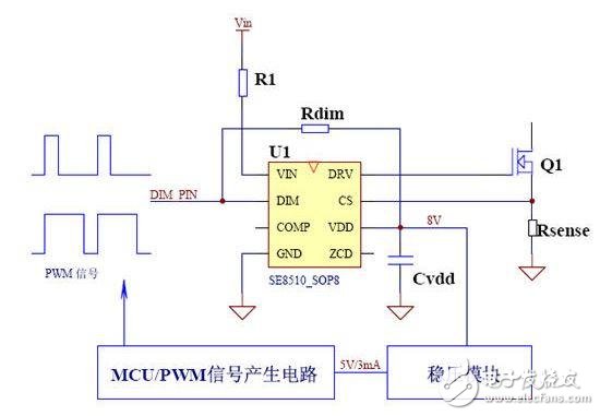
Figure 1: SE8510 Flyback Isolation Circuit Diagram
2. Support PWM to adjust output current and change LED brightness
PWM dimming can be achieved by adding a low frequency square wave signal through PIN DIM. When the PWM signal is zero, the gate driver is turned off, and when the PWM signal is high ("300 mv), the gate driver is enabled. The LED current is proportional to the duty cycle of the PWM wave. In order to reduce the frequency interference, it is recommended that the frequency of the PWM control signal be set between 200HZ and 500HZ.
3. Provide MCU power supply system to solve the power supply problem of MCU control system
As shown in Figure 2, the schematic diagram of the MCU output PWM control signal control system is traditionally used. In the design, you will encounter the need to supply power to the MCU.
(1) The constant current output of the AC-DC system is designed to control the brightness of the LED. However, the power supply of the MCU is selected. A separate set of AC-DC Power Supplies is used as the power supply system for the MCU. This has resulted in increased costs and has evolved into the design of two independent AC-DC power supplies.
(2) Supply power from the AC-DC LED constant current drive power supply. Power is supplied from the auxiliary winding, and the power supply of the MCU and the AC-DC control IC are taken from the same winding end. However, when the MCU issues a control signal to control the AC-DC control IC to stop the AC-DC system, the auxiliary winding will also be powered down. Causes power outage of the MCU.
(3) Place the MCU control in the AC-DC secondary section. Similarly, when the AC-DC system is turned off, the output voltage will also drop. Usually the customer design uses the output to increase the output capacitance, which makes the discharge slower, thus providing the MCU. The output capacitor volume and cost are increased.
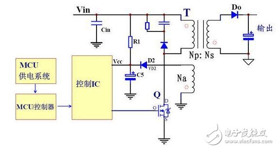
Figure 2: Traditional MCU output control signal control system diagram
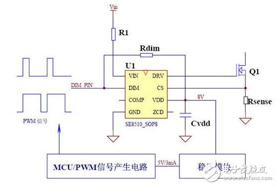
Figure 3: The SE8510 provides MCU power supply to solve the problem of system power failure MCU power supply
As shown in Figure 3, the SE8510 uses a proprietary power supply system patented technology. Using a rugged high-voltage isolation process, it can withstand an input voltage of up to 450V with a wide input voltage range of 8-450V. A high voltage power supply system from VIN-VDD has been added to the IC. The VDD voltage is 8V and has a load capacity of 5mA (due to the power dissipation of the SOP8 in the form of an IC package). Sufficient MCU and some PWM generation circuits work normally (MCU operating current 2mA).
The VDD voltage is reduced to 5V through a small voltage regulator module, such as the 7805, or a regulator consisting of a triode. It is provided to the MCU or PWM signal generation circuit. For example, the NE555 generates a PWM duty cycle adjustable generation circuit. When the MCU issues a PWM low signal, the SE8510 system is turned off. However, since the internal VIN-VDD high voltage module of the IC operates independently, VDD maintains a voltage of 8V, and the MCU is powered off, causing the program to restart. Moreover, it saves the high cost and large volume brought by the circuit of the external power supply system.
Solar system Pump Inverter,Solar System Power Inverter,Solar Control Inverter,Solar Inverter With Charger
GuangZhou HanFong New Energy Technology Co. , Ltd. , https://www.gzinverter.com