In recent years, the luminous efficiency of high-power white LEDs has made great progress. From the original 40Im/W to 60Im/W, and from 601m/W to 80Im/W, some 1W cold white LEDs have a luminous flux of ≥100Im at 350mA, that is, their luminous efficiency can reach above 100Im/W. What is the concept of the luminous efficiency of cold white LEDs reaching 60-80Im/W? Its luminous efficiency has exceeded the luminous efficiency of self-ballasted fluorescent lamps (energy-saving lamps), and the luminous efficiency of general energy-saving lamps is 50 to 701 m/W. In other words, it is more energy efficient and brighter than energy-saving lamps.
In the design of LED luminaires, especially lamps of dozens of watts to tens of watts are now gradually adopting high-power LEDs, which not only improves brightness but also improves reliability.
This article introduces Cree's 4W×LampXR-E high-power white LED, which has high performance and high reliability. It has a variety of illuminating colors, only white LEDs are introduced here, the model number is ×REWHT-L1.
Main features and applications
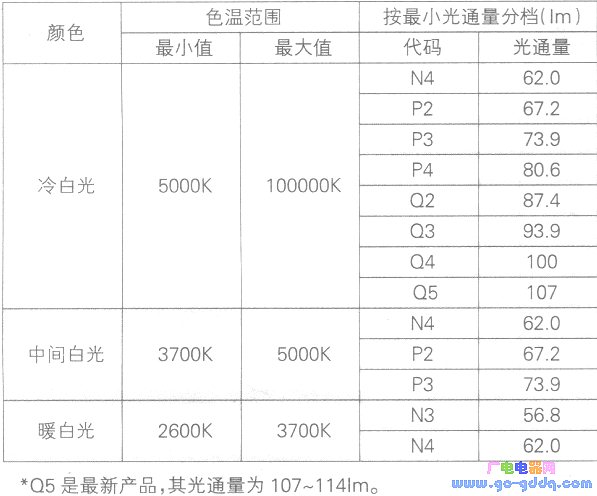
The main features of XREWHT-L1 white LED: it can produce white light with color temperature of 2600K to 10000K (divided into cool white, intermediate white and warm white); three different color temperature products are divided according to their luminous flux size to meet different requirements of users. As shown in the above table, the highest luminous flux of cold white light is greater than 100 μm, and its typical luminous flux is 801 m (light flux at 350 mA): forward current range is 350 to 1000 mA; internal structure has good thermal conductivity, with a bottom area of ​​7 mm × 9 mm. The thermal resistance RJ_C of the LED from the die to the bottom soldering surface is only 8 °C / W, which is the lowest in the industry; it can be reflowed: the lifetime is 50,000 hours when the brightness is attenuated to 70%; it meets the requirements of RoHS.
The main application areas of the white LED: portable lamps (mineral lamps, flashlights, emergency lights, etc.), outdoor lamps (street lights, advertising and signage projectors, etc.), indoor lights (reading lights, transportation vehicles, such as cars, boats, Lighting lights in the aircraft, etc.).
The main parameters
The main parameters of the white LED: the thermal resistance from the PN junction to the bottom surface is 8 ° C / W; the voltage temperature coefficient is -4. OmV/°C; viewing angle 900; forward current IF maximum value 1000mA (cold white light ≥5000K), 700mA (intermediate white light and warm white light color temperature ≤5000k); current can reach 1.8A at 10% duty cycle, lkHz pulse Reverse withstand voltage 5V; typical forward voltage drop at different currents: 3.3V at 350mA, 3.5V at 700mA, 3.7V at 1000mA; maximum forward voltage drop is 3.9V; junction temperature is 150 °C.
Main characteristic curve
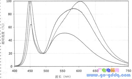
1. The spectrum of three different white light colors is shown in the figure above. The color temperature of the blue curve is 5000 to 10000K, the color temperature of the green curve is 3500 to 5000K, and the color temperature of the red curve is 2600 to 3500K.
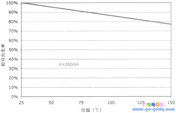
2. The junction temperature and relative light output curve of the LED are shown in the figure above. If the light-emitting rate at the junction temperature TJ=25° C. is 1, it decreases as the TJ increases. It can be seen from the figure that when TJ = 100 ° C, the light extraction rate is reduced by about 20%. In addition, the increase in TJ also affects the life of the LED. Therefore, when designing the heat dissipation, it is appropriate to set the TJ to 80 to 85 °C.
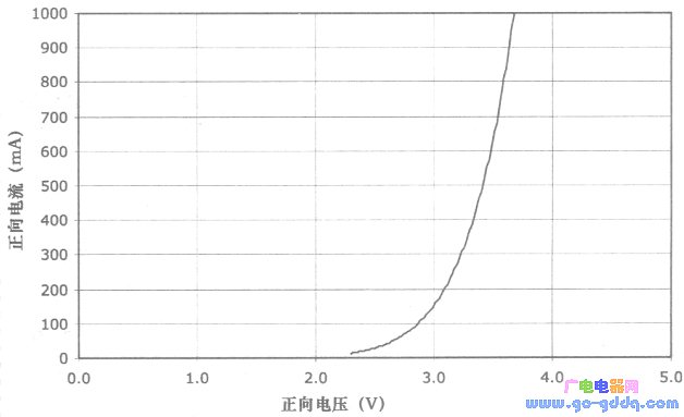
3. The forward voltage and forward current characteristics (output characteristics) are as shown in the figure above. This is a typical characteristic curve with an operating current in the range of 350 mA to 1000 mA and a forward voltage drop VF in the range of 3.3 to 3.7 volts. If you choose a different operating current IF, you can use Figure 3 to find the corresponding forward voltage drop VF value. The PD value can be obtained by using the formula of the dissipated power PD=IF×VF (the PD is related to the heat dissipation area of ​​the PCB for heat dissipation).
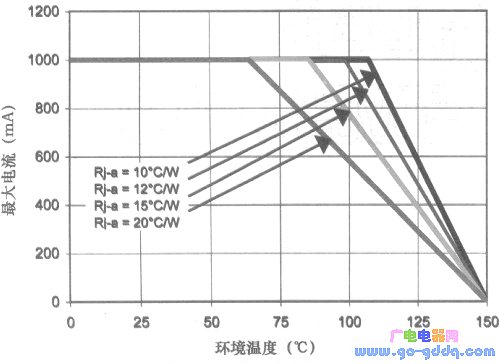
4. The derating characteristics of cool white light are shown in the above figure. The derating characteristics of the intermediate white and warm white light are shown in the figure below. The maximum operating current IF is different under different ambient temperature TA and thermal resistance RJA under different heat dissipation conditions. For example, if RJ-A=15°C/W in Figure 4, if the ambient temperature TA=75°C, the maximum operating current IF can reach 1000 mA; if RJ-A=20°C/W, the same When TA=75°C, the maximum working current IF value needs to be reduced to 870mA (if it is not derated, it will overheat and TJ will rise).
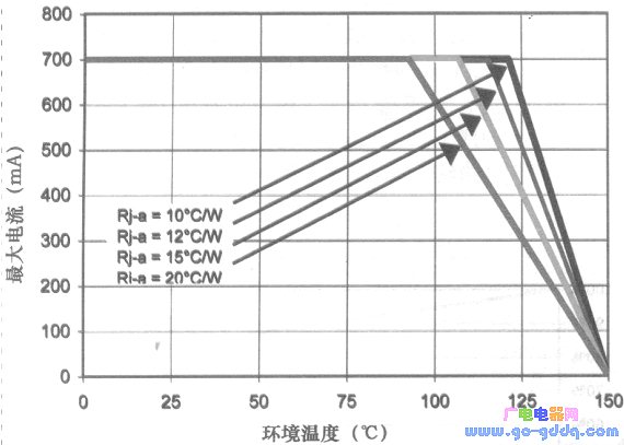
RJ-A is the thermal resistance from the junction temperature TJ of the PN junction of the LED to the PCB through the substrate of the LED and then from the PCP to the ambient temperature TA. If the thermal conductivity of the PCB is good (for example, the PCB of the double-sided copper layer is better than the thermal conductivity of the single-layer PCB) and the heat dissipation area is large, the RJ-A is small, and the RJ-A calculation is described below.
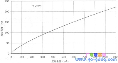
5. The characteristic curve of the forward current and the relative brightness of the LED is shown in the figure above. The relative brightness at 350 mA in the above figure is 100%, and the slope decreases as the current increases. For example, when the current is increased from 350 mA to 700 mA, the brightness is not 200%, but 170%. That is, the brightness increases as the current increases, but does not increase proportionally. As the current increases, the junction temperature rises and its light output rate decreases. 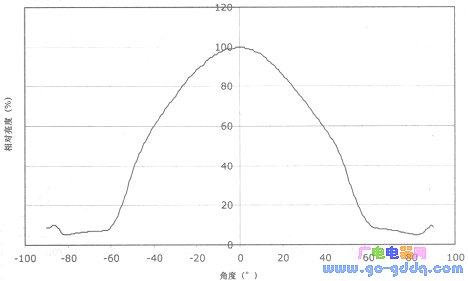
6. The LED viewing angle described in this document is 90°. The relative bright characteristics at different angles are shown in the figure above.
Shape and pad size
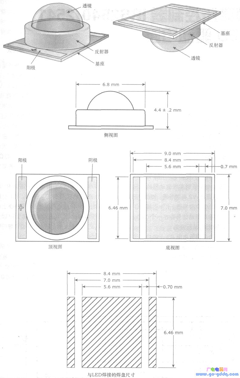
The shape and related dimensions of the XREWHT-L1 are shown above. In the figure, there is a "+" symbol for the anode of the LED. On the bottom surface, there are two narrow strips of LED anode and cathode pins. The middle of the wide area is soldered to the PCB heat-dissipating copper plate (reflow soldering). It is better to dissipate heat from the PCB through the solder layer at the bottom of the LED. The pad size is shown as a diagonal line.
RJ-A calculation
It can be seen from Fig. 4 and Fig. 5 that different RJ-A have an influence on the operating current IF. Here is a method for calculating TJ-A by simply measuring the temperature TC at the bottom of the LED and the solder joint of the PCB.
A PCB with a double-sided copper layer of 45×45 mm is used as the test PCB, and the front side (the surface of the soldered LED) is shown in the figure below, and the copper layer on the back side is all used for heat dissipation. The temperature of Te is measured by a K-type thermocouple point thermometer at the soldering layer of the soldering LED (as indicated by the arrow in Fig. 9, the measuring point of the K-type thermocouple is preferably soldered on the PCB).
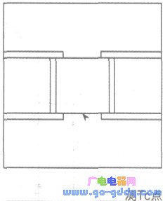
The current IF and the voltage VF are measured by energization on the test board, and the temperature Tc is measured after stabilization.
RJ-A=RJ-C+(Tc-TA)/PD type RJ-C is the thermal resistance of the LED itself, RJ-C=8°C/W, the ambient temperature TA is measurable, PD=IF×VF If the IF × VF is measured, the RJ-A can be calculated after the temperature Tc is measured. If RJ-A requires 15°C/W at the time of design, and the RJ-A calculated after measuring Tc is greater than the required RJ-A value, the heat dissipation area of ​​the PCB is insufficient or the heat dissipation performance of the PCB material is poor. It is possible to increase the heat dissipation area of ​​the PCB by replacing the PCB of the aluminum substrate or not replacing the PCB. If the RJ-A is calculated to be too large after measuring Tc, a heat sink can be added after the PCB board, as shown in the figure below.
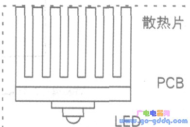
Through the above tests, calculations and improvement measures, a suitable heat dissipation structure can be designed.
If you want to know the junction temperature after calculating RJ-A, what is it? By calculation: RJ-A=(TJ-TC)/PD+(TC-TA)/PD, if the calculated TJ is suitable at 80-85 °C, if TJ=85°C or less is required, it is tested and calculated. The TJ should be equal to or less than 85 ° C, otherwise the value of (TC-TA) / PD should be lowered.
Small computer system interface (SCSI) is an independent processor standard for system level interfaces between computers and intelligent devices (hard disks, floppy drives, optical drives, printers, scanners, etc.). SCSI is an intelligent universal interface standard.
The last SCSI device in the SCSI chain uses a terminator, and the intermediate device does not need a terminator. Once the terminator is used by the intermediate device, the SCSI card cannot find the future SCSI device. If the last device does not use a terminator, SCSI will not work properly. Terminator is composed of resistors, located at the end of the SCSI bus, to reduce the mutual influence of the signal, maintain the constant voltage on the SCSI chain.
Most of the SCSI devices have built-in terminators and use a jumper to control on / off. The SCSI device is highly intelligent and can automatically control the terminator on / off. For example, if a hard disk is connected to a CD-ROM, the CD-ROM can work normally regardless of whether the terminator of the hard disk is on or off. However, when two hard disks are connected, the situation becomes more complicated. Before two Seagate hard disks are connected, one hard disk terminator must be off. Before a Seagate hard disk is connected to a quantum hard disk, a hard disk terminator can work normally regardless of whether it is on or off.
SCSI-90°DIP Section
ShenZhen Antenk Electronics Co,Ltd , https://www.pcbsocket.com
