The brake energy recovery problem is of great significance for improving the energy utilization of EV. When an electric vehicle adopts electric braking, the driving motor operates in a power generation state, and it is essential to extend the driving distance of the electric vehicle by feeding back some of the kinetic energy of the automobile to the battery to charge it. Foreign studies have shown that under the conditions of urban conditions with more frequent braking and starting, the effective recovery of braking energy can extend the driving distance of electric vehicles by 10% to 30%.
This article refers to the address: http://
At present, domestic research on braking energy recovery is still in its infancy. Braking energy recovery should consider various aspects such as vehicle dynamics, motor power generation characteristics, battery safety assurance and charging characteristics. It is difficult to develop a system that has both practical utility and driver's operating habits. This article has made some positive explorations on the above issues and has drawn some useful conclusions.
1 brake mode
Electric vehicle brakes can be divided into the following three modes, and different control strategies should be adopted for different situations.
1.1 sudden braking
The sudden braking corresponds to a process in which the braking acceleration is greater than 2 m/s2. For safety reasons, the brakes should be mainly mechanical, and the electric brakes should work at the same time. In the case of sudden braking, the corresponding mechanical braking force can be provided by the ABS control on the vehicle according to the initial speed.
1.2 medium and light brakes
The medium and light brakes correspond to the braking process of the car under normal working conditions and can be divided into a deceleration process and a stop process. The electric brake is responsible for the deceleration process, and the stopping process is completed by the mechanical brake. The switching points of the two brakes are determined by the motor's power generation characteristics.
1.3 Brakes when the car is going downhill
The long downhill slope of a car generally occurs when the downhill slope of the Panshan Highway. When the braking force is not required, it can be completely provided by the electric brake. Its charging characteristics are characterized by a small feedback current but a longer charging time. The limiting factor is primarily the maximum chargeable time of the battery.
Since electric vehicles mainly work in urban conditions, this paper focuses on medium and light electric brakes.
2 Brake energy recovery constraints
A practical energy recovery system should meet the following requirements:
(1) Meet the safety requirements of the brakes and meet the brakes of the driver.
The safety requirements are the first in the braking process. Need to find the best coverage of electric brakes and mechanical brakes, and recover as much energy as possible while ensuring safety. The braking process of an electric vehicle with an energy recovery system should be as close as possible to the conventional braking process, which will ensure that the system is attractive and acceptable to the public in practical applications.
(2) Consider the power generation operating characteristics and output capability of the drive motor.
Commonly used in electric vehicles are permanent magnet DC motors or induction asynchronous motors. The corresponding control measures should be adopted for the power generation efficiency characteristics of different motors.
(3) Ensure the safety of the battery pack during charging and prevent overcharging.
The batteries commonly used in electric vehicles are nickel-hydrogen batteries, lithium batteries, and lead-acid batteries. When charging, avoid damage to the battery due to excessive charging current or excessive charging time.
The energy recovery constraints are obtained from the above analysis:
(1) The maximum charging current acceptable to the battery, depending on the depth of discharge of the battery.
(2) The maximum charging time acceptable for the battery.
(3) The rotational speed of the motor at the time of energy recovery stop and the corresponding charging current value.
The prototype of this project is XL pure electric vehicle. The drive adopts asynchronous AC motor. The rated power is 20kW, the peak power is 60kW, the rated torque is 53Nm, the peak torque is 290Nm, and the continuous output is three times the rated torque time is not less than 30s. The rated speed is 3600r/min and the maximum speed is 9000r/min. The battery uses 24 100Ah NiMH batteries, and its instantaneous charging current can reach 1.5C (C is the battery discharge rate), which is 150A. When the charging current is 0.5C, it can be safely charged. Experiments show that the charging current is less than 6A when the motor speed is 500r/min. This point can be set as the switching point between the electric brake and the mechanical brake. 3 Brake energy recovery control algorithm
3.1 Analysis of braking process
It can be derived that the primary brake recovers energy E=K1K2K3 (ΔW-FfS).
During the specific braking process, the kinetic energy attenuation ΔW of the vehicle body is constant. The mechanical transmission efficiency K1 and the rolling friction force Ff of a particular vehicle type are substantially fixed. For the battery, the braking energy recovery corresponds to a short time (not more than 20s) and a large current (up to 100A) charging, so the energy recovery constraint (2) is negligible, and the charging efficiency K3 can also be considered constant. For the motor, its power generation efficiency K2 changes with the change of the speed and torque during the braking process. The braking distance S depends on the magnitude of the braking force and the length of the braking time.
From the above analysis, if the battery state (including the depth of discharge, initial charging current intensity) allows, the recovery energy is only related to the generator power generation efficiency and braking distance. The motor speed can be controlled by adjusting the motor braking torque while meeting the braking time requirements.
3.2 Control algorithm
The control strategy can be described as: when the braking requirements are met (determined by the medium and light brake gears), the optimal braking force is determined according to the different values ​​of the energy recovery constraints (1) and (3), so that the recovered energy The maximum is reached, that is, the current to time integral is maximized. In order to comply with the usual braking habits, the braking force increases linearly with the braking time, ie Fj=Fo+Kt. The problem is converted to find the optimal initial value Fo of the braking force and the coefficient of increase K of the braking force.
China's commonly used car cycle 25 working conditions [1] stipulates that the maximum speed of the car does not exceed 60km / h, the acceleration range of -1.5m / s2 ~ 1.5m / s2. In order to reflect the typicality of automobile braking under urban conditions, and to ensure safety and stability, the following braking process is considered: the initial braking speed is 60km/h (corresponding to the motor speed is 4500r/min), and the electric braking ends. The speed is 5.4km/h (corresponding to the motor speed is 500r/min), and the absolute value of the required acceleration is less than 2m/s2, and the speed curve is as smooth as possible. The brake time is 8s~12s for medium-duty brakes and 12s~18s for mild gear brakes. Only the moderate gear brakes are discussed below, and the mild gear brakes are similar.
When the nickel-hydrogen battery (100Ah) is discharged at a normal temperature of 0.5C, the battery cell voltage varies from 12 to 15V, but the battery mainly works on the platform section, that is, 12.2 to 13V. To facilitate discussion of the problem, the battery terminal voltage is considered to be 12.5V and the total voltage is equal to 300V. Based on this assumption, the calculated charge current error does not exceed 6%.
When the motor is running at different speeds and torques, the measured efficiency curve is similar to the exponential function. For convenience of processing, the efficiency curve can be linearly fitted into three functions as follows (the fitting error does not exceed 5%, where n is the instantaneous motor speed):

Corresponding to this, the braking process can be divided into three phases:
The first stage: the motor speed varies from 4500 r/min to 3600 r/min, the motor power generation efficiency is 0.9, and the braking time t1 ≤ 3 s is required.
The braking torque is 60Nm, that is, F0=1860N, K=20, and t1=2.62s is obtained, and the average acceleration is about -1.29m/s2. The calculation shows that the charging current I monotonically decreases, IMax = It = 0 = 75.75A.
The second stage: the motor speed varies from 3600r/min to 1500r/min, and the power generation efficiency of the motor ranges from 0.9 to 0.82, and the braking time is required to be t2 ≤ 5s.
At this point the problem comes down to the optimal control problem under constraints. According to the simulation calculation, the recovered energy value increases monotonously with the increase of F0 and K, and is mainly determined by F0. When F0 is small, the change of K has a greater influence on the braking time. Since the motor can operate at three times overload (140Nm), the maximum braking force is 4300N. When F0=4300N and K=30, the recovered energy takes the maximum value, which is 274.3 (unit: amps/As), and the average acceleration is -2.83 m/s2. In order to meet the requirements of brake stability, take F0=2300N, K=50. The braking time is 4.71 s. At this time, the recovered energy is 262.8 As, which is 4.2% lower than the maximum value, and the average acceleration is -1.68 m/s2, which is only 59.3% of the maximum value. The maximum charging current at this stage is 76.9A. In order to accurately describe the effect of energy recovery, a new unit "Amp / As" (ie, the time integral of the current in seconds) is introduced to measure the energy.
The third stage: the motor speed varies from 1500r/min to 500r/min, and the power generation efficiency of the motor ranges from 0.82 to 0.6, and the braking time is required to be t3 ≤ 2s.
According to the analysis method of the second stage, when F0=3000N and K=30, the braking time is 1.88s, the recovery energy is 42.1As, and the average acceleration is -2.01m/s2. At this time, the recovered energy is reduced by 2.3% from the maximum value, and the average acceleration is 74.1% of the maximum value, and the maximum charging current at this stage is 35.9A.
4 simulation models and results
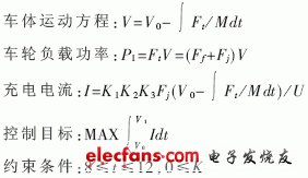
According to the theory of automobile dynamics [2] and combined with other related equations, the simulation model can be obtained:
Driving force: Ft=Ff+Fj+Fi+Fw
Among them, Ft is the combined force of the driving forces acting on the wheel, Ff is the rolling friction force, Fj is the acceleration resistance, Fi is the slope resistance, and Fw is the air resistance. In urban conditions, Fi and Fw can be ignored.

Among them, the body mass is M, the instantaneous vehicle speed is V, the initial braking speed is V0, the vehicle speed is V1 at the end of electric braking, the charging current is I, and the battery terminal voltage is U. Other symbols have the same meaning as before.
The simulation model is established in the Simulink environment, and the motor speed curve is shown in Figure 1. The charging current curve is shown in Figure 2. The recovery energy curve is shown in Figure 3.


 5 Evaluation of the effectiveness of braking energy recovery control algorithm
 Taking the typical process of electric braking with an initial speed of 60km/h as an example, it can be obtained through simulation calculation that the recovered energy accounts for 65.4% of the total kinetic energy of the vehicle body, and the remaining 34.6% is the loss during mechanical braking and electric braking. Taking the 25-cycle condition of China's car as an example, considering the frictional resistance and the efficiency of each part, the recovered energy accounts for 23.3% of the total energy consumption.
The experiment proves that the braking energy recovery control strategy proposed in this paper is simple and effective. Under typical urban conditions, the XL pure electric sedan equipped with an energy recovery system operates reliably and can extend the driving range by more than 10%.
6 Discussion of other related issues
Lithium batteries are also the common power source for EVs because of their high specific energy. The experiment proves that the instantaneous (20s) charging current of the lithium battery developed in China can reach 1C. For the commonly used 80Ah lithium battery, the maximum charging current is about 80A. However, for safety reasons, if the brake energy recovery system is used in a lithium battery system, strict current limiting measures are required or the electric brakes and the mechanical brakes are simultaneously acted upon.
Another case of brake energy recovery is the slow down slope of the car. In China, the slope of urban roads is not more than 8%. Under this condition, if the EV downhill speed is 30km/h (n=2200r/min, efficiency=0.847), the brake charging current is 37.6A, which is for NiMH batteries. If you can't say 0.4C, you can safely continue charging.
Although this topic is aimed at pure electric vehicles, the above discussion is equally applicable to various hybrid vehicles because the energy recovery rules of hybrid vehicles and pure electric vehicles are similar. The main difference is that the battery discharge rate is different.
new smart watch,sport smart watch,smart watch supplies,phone smart watch for Iphone
Shenzhen Konchang Electronic Technology Co.,Ltd , https://www.konchangs.com
