Abstract: Radio and television stations (stations) are the key departments of the country and have a high level of security. Video surveillance is an important technical guarantee. This paper mainly introduces the design and implementation of a core component based on MPEG-4 video codec card in a video surveillance system.
Keywords: broadcast television station; video surveillance; codec card
This article refers to the address: http://
0 Introduction The normal operation of the broadcasting and television system and the safe broadcast of the program require a high-level security system. In order to ensure the safety of radio and television organizations, the Ministry of Public Security has issued special documents such as the Regulations on the Protection of Radio and Television Facilities, the Risk Levels of Critical Parts of the Radio, Film and Television System, and the Level of Security and Protection, according to its risk prevention level. At the same time, combined with the actual situation of each unit, develop its own radio and television monitoring system. The radio and television center building is the base for the production, editing and broadcasting of radio and television. The work area is generally designated as a secondary risk unit, and a video surveillance system needs to be established in the building work area. At the same time, each station establishes its own video surveillance system for real-time monitoring of the main control room, the broadcast room, and the computer room. This paper mainly introduces the design and implementation of a video component codec in the core component of a video surveillance system.
MPEG-4 is one of the most important and influential international standards for multimedia data compression coding. Compared with the traditional multimedia monitoring system, the emerging MPEG-4 multimedia monitoring system based on embedded technology has the advantages of small size, no need for dedicated personnel on site, low cost, high stability, good real-time performance, better storage and network transmission. . Therefore, we design and implement a video codec card based on the MPEG-4 standard. The ASIC-dedicated chip that implements the MPEG-4 image algorithm has the characteristics of low cost, low power consumption, high stability, clear image, good expansion performance, and high security. We are using VW2010.
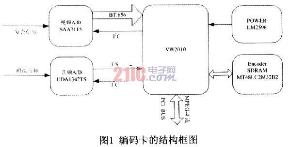
1 MPEG-4 encoding card design and implementation The structure of the encoding card is shown in Figure 1, mainly including audio and video A / D, compression chip VW2010 and its required SDRAM, as well as power clock and other modules.

Since the input and output of audio and video of VW2010 are digital format, the input and output of video is ITU-R BT. In the 656 format, the audio input and output is in the I2S format. Therefore, it is necessary to perform analog-to-digital conversion on audio and video analog input signals and form I2S format audio data, ITU-R BT. The 656 format video data is encoded as input data of the VW2010. Therefore, it is necessary to select some peripheral chips and cooperate with VW2010 to complete the entire encoding process.

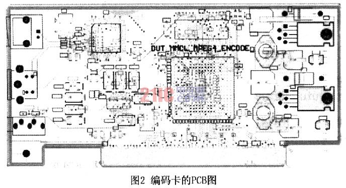
The system block diagram of the code card is shown in Figure 1, and the PCB diagram is shown in Figure 2. As the core of the system, VW2010 connects to the host through the PCI bus, and mainly receives the initial configuration data and real-time control information sent from the host to the VW2010. At the same time, the VW2010 compressed MPEG-4 video stream and audio stream are also sent through the PCI bus. To the host. VW2010 controls each audio and video A/D through the I2C bus, and initializes its internal registers.
After the analog audio and video signals are sampled and encoded by audio and video A/D, the audio signal becomes I2S format data into VW2010, and the video signal becomes 8-bit parallel ITU-R BT. The data of 656 format enters VW2010. VW2010 synchronizes the audio and video according to the encoding format and working mode transmitted from the host according to the programming setting, and then obtains MPEG-4 data and sends it to the host. In addition to the MPEG-4 encoding chip VW2010, it is necessary to select separate components such as video A/D chip, audio A/D chip, memory SDRAM chip, power chip, and resistor and capacitor.
Video A/D chip: Select Philips SAA7115, which has 6 analog video signal inputs (such as 6 composite video or 2 S-Video and 2 composite video, 1 S-Video and 4 composite video inputs), two A 9-bit analog-to-digital converter, the input video signal can be selected by I2C, the bus sets the internal registers. It can automatically identify various PAL signals and NTSC and SECAM signals and decode them into ITU-RBT. 60l, ITU-R BT. Video data in 656 format. In order to better separate the luminance and chrominance of the composite video signal, the chip has an adaptive comb filter. Video VBI data can also be decoded. It is a relatively high-end video A/D chip.
Audio A/D chip: The audio A/D chip uses Philips' UDAl342TS, which has a 4-channel analog-to-digital converter (ADC) and a 2-channel digital-to-analog converter (DAC). With low voltage and low power consumption, it supports 24-bit I2S data format and can be controlled by I2C bus. Although the chip has both A/D and D/A functions, the audio sampling rate must be the same when A/D and D/A are working at the same time. For this reason, this design only uses its A/D: function. For D/A, CS4331-KS is used. The chip is a complete stereo analog-to-digital converter that inputs audio data in I2S format, outputs left and right stereo, has a dynamic range of 96dB, 24-bit conversion, 5V power supply, and a small package with only 8 pins.
Memory chip: When VW2010 performs codec, it needs to access video data, so each codec needs 4~8MB of memory. This design uses MT48LC2M3282 chip.
Power chip: 3.3V and 1.8V power supplies are required in this system. The 5V power supply on the PCI bus needs to be converted. Taking into account the power consumption and power efficiency of each chip, power supply cooling and other issues, the switching power supply LM2596 is used as the power chip.
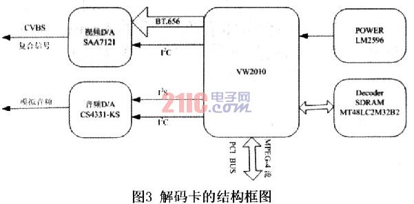
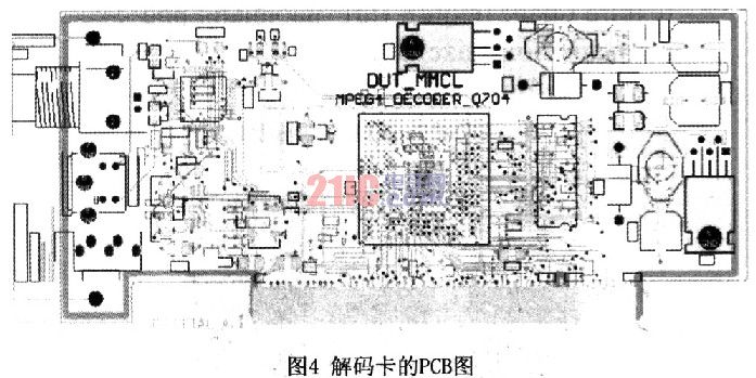
2 MPEG-4 decoder card design and implementation Decoding is the inverse of the encoding process, the block diagram of the decompression card is shown in Figure 3, PCB diagram shown in Figure 4. VW2010 is the core processing chip of the decompression card. The MPEG stream data to be processed is input through the integrated PCI interface of the chip. In addition to MPEG decompression, the VW2010 also provides control of the audio ADC chip (via the I2C bus). VW2010 decompresses MPEG stream data to produce standard ITU-656 digital video signals and standard I2S digital audio signals; the generated ITU-656 digital video signals are sent directly to the real-time monitoring subsystem for picture segmentation; the resulting I2S The digital audio signal generates an analog audio signal through the audio DAC circuit, and the analog audio signal is directly sent to the real-time monitoring subsystem audio selection sub-module selection output after output processing.


The video D/A chip uses Philips' SAA7121, which is available for ITU-R BT. The video data of the 656 format is encoded into a composite video and a video signal of the S terminal. It has three 10-bit precision ADCs, one ADC outputs a composite video signal (CVBS), and the other two output the S terminal's luminance (Y) and chrominance (C) signals. The initialization of the chip is set by I2C, bus. Audio D/A uses CS4331-KS. The chip is a complete stereo ADC, input audio data in I2S format, output left and right stereo, with 96dB dynamic range, 24-bit conversion, 5V power supply, small package, only 8 pins. It should be noted that the audio A/D chip Philips' UDAl342TS also has D/A function, but when A/D and D/A work simultaneously, the audio sampling rate must be the same. For this reason, we choose CS4331-KS.
The codec card has a very flexible choice in the actual system construction, because the PCI interface structure can be combined with multiple platforms such as an embedded communication platform, a PC platform, and an industrial computer. Both local storage and network transmission are possible. The codec card separation design can effectively reduce the cost. It can be connected to the decoder at the far end of the network after the end of the uploading network, and then the analog signal is directly connected to the monitor display, so that the monitoring system can be connected with the previous module monitoring system. The monitor and TV wall are connected, no PC is required to participate, and the requirements for seamless upgrade are achieved. The MPEG-4 can be softly decoded by directly accessing the PC at the remote end of the network. In the practical application, good results have been achieved. What needs to be improved is the application and development of the upper layer image management software.
Passive Stylus Pen,Custom Stylus Pen,Stylus Pen For Surface,Smart Stylus Pen
Shenzhen Ruidian Technology CO., Ltd , https://www.wisonen.com
