There are many subsystems of the hybrid hybrid system. The vehicle controller is used as a management system to realize the driver's driving demand and energy safety. It is necessary to coordinate the reasonable distribution of the power of the engine, torque, motor and battery under different working conditions. Brake energy feedback and control of peripheral equipment (such as air conditioning, lighting) to achieve the best energy-saving emissions. The complexity of the system task and the strong electromagnetic interference environment pose significant challenges to the real-time and reliability of the vehicle controller. The traditional single-task cycle program control mode is difficult to meet the requirements, so the author uses open source embedded. The operating system μC/OS-II designs the vehicle controller system software.
1 vehicle system structure
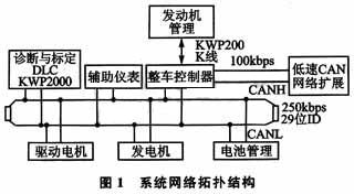
The fully-hybrid sedan developed by the company is a major project in Tianjin, with the Great Wall Harvard SUV sedan as the platform. The vehicle's power system is mainly composed of an engine, an AC motor, an alternator, a high-performance nickel-hydrogen battery, a planetary power distribution mechanism, and a DC-AC inverter. The vehicle controller uses the bus to exchange information with the engine management system, the motor controller and the power battery management system, and reserves one channel of CAN for later communication with the body system.
The vehicle controller controls the operation of each subsystem according to the driver's input signal, combined with the battery pack status and the current operating state of the vehicle, and achieves the goal of energy saving and emission reduction according to certain strategies. The system network topology is shown in Figure 1.
2 vehicle controller hardware design
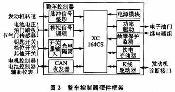
According to the modular principle, the hardware design of ECU can be divided into the following functional modules: microcontroller module, data acquisition module, power drive and protection module, D/A conversion module, power module, communication module, display and alarm interface. Calibration diagnostic interface, etc. Infineon's XC164CS microcontroller is based on the enhanced C166SVZ core and outperforms other 16-bit microcontrollers: integrated DSP functionality, extended interrupt handling, powerful on-chip peripherals, and high-performance on-chip Flash ,as shown in picture 2.
3 μC/OS-II transplantation
The μC/OS-II embedded real-time operating system is written in ANSI C language and has good readability and portability. It is not required for hardware resources and can be implemented on most 8-bit and 16-bit microcontrollers. transplant.
3.1 μC/OS-II startup
First, the hardware driver is called to initialize the hardware, and then the system initialization function OSlnit() is called to initialize all the variables and data structures of μC/OS-II.
Create an application task before starting μC/OS-II. OSlnit() establishes the idle task idletask, which is always in the ready state. The priority of the idle task OSTaskIdle() is set to the lowest, ie OS_LOWEST_PRIO. Multitasking startup requires the user to do so by calling OSStart(). Of course there are other settings, which are not covered here.
3.2 μC/OS-II transplantation
The migration of the μC/OS-II operating system on the XC164CS microprocessor mainly implements three files OS_CPU.H, OS_CPU_C. C, OS_CPU A. ASM processing.
3.2.1 header file INCLUDES.H
The INCLUDES.H header file should be included in line 1 of all C files. Although including unrelated files may increase the compilation time of the file, it enhances the portability of the code. Users can edit to add their own header files, but they must be added at the end of the header file list.
3.2.2 OS_CPU.H file
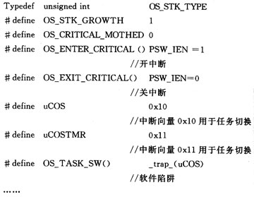
The OS_CPU.H file contains definitions of processor-related constants, macros, and structures. For the XC164CS processor, the stack data type is defined as 16 bits, and the stack is decremented downwards; the two macros OS_ENTER_CRITICAL() and OS_EXIT_CRITICAL() that control the interrupt of μC/OS-II are defined as microcontroller off (SETC) and on (CLRC). The interrupted instruction; declares the OS_TASK_SW() function, and the entry of the interrupt service routine ISR points to the function OSCtxSw().
3.2.3 OS CPU A.ASM
The μC/OS-II port requires the user to write four assembly language functions: OSStartHighRdy(), OSCtxSw(), OSIntCtxSw(), and OSTickISR().
(1) OSStartHighRdy()
Call this function to start the task with the highest priority in the ready state. Since the real-time operating system is a function that does not return, after the call, the return address of the top of the stack stack needs to be removed, and then the user call function OSTaskSwHook() is executed, and finally the multi-tasking is started, and the pointer of the task with the highest priority is obtained, according to the pointer. All registers are restored from the task stack, and after the recovery is complete, the interrupt is returned and the ready state task is run.
(2) OSCtxSw()
When switching from a low-priority task to a higher-priority task, the task switching function OSCtxSw() is called to save the contents of the processor and the task pointer to the task stack of the current task, and then execute the user call function OSTaskSwHook(), and finally To resume the contents of the registers and stack in the task stack of the task to be executed, execute the interrupt return instruction to start running the new task.
(3) OSIntCtxSw()
This article refers to the address: http://
When it is necessary to switch to a higher priority task after an interrupt occurs, the interrupt level task switching function OSIntCtxSw() is called, and then the user call function OSTaskSwHook() is executed. Because the function is called in the interrupt program, there is no need to save the register of the interrupt task; when the interrupt subroutine calls the function OSInExit(), the return address is pushed onto the stack, and there is no need to return here, so it must be from the stack. Clean up the return address.
(4) OSTickISR()
OSTickISR() is the clock tick interrupt service routine in μC/OS-II. This function is called at each clock tick, decrementing the delay for each task that is delayed, and checking that all tasks in the delayed state end up as ready tasks. Then call OSIntExit(), and if there is a higher priority task ready, OSIntExit() will schedule the task. Instead of returning to the caller, OSIntExit() restores the CPU scene with the contents of the new task stack and returns to execute the new task.
3.2.4OS_CPU_C.C
Users need to write six C language functions OSTaskStkInit (), OSTaskCreateHook (), OSTaskDelHook (), OSTaskSwHook (), OSTaskSatHook (), OSTimeTickHook (). Among them, the only necessary is OSTaskStkInit (), the other five must be declared, but can not contain code.
OSTaskStkInit() is called by the task creation function OSTaskCreate() or OSTaskCreateExt() to initialize the task stack when each task is created. Start running this task is to simulate the interrupt return, restore the value saved in the stack after initialization to each register. When the task stack is initialized, the task code start pointer (Ptask), parameter pointer (Pdata), and task stack stack top pointer are passed. After the task stack is initialized, a new stack top pointer is returned, and OSTaskCreate() or OSTaskCreateExt() saves it to OSTCB.
Five hook functions can be created in the OS_CPU_C.C file, provided that the constant OS_CPU_HOOKS_EN is enabled in the configuration file.
At this point, the migration of the μC/OS-II operating system is basically completed.
4 vehicle controller software multitasking design
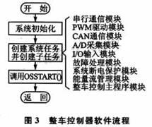
The vehicle controller software design uses the real-time operating system as the development platform to decompose the application into multi-tasking, which simplifies the design of the system software, ensures the real-time performance of the vehicle control system, and improves the stability and reliability of the system. The main program flow of the entire system is shown in Figure 3.
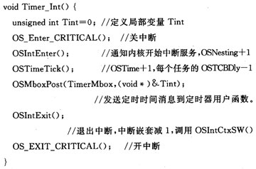
4.1 Timer Module
The main function of the timer is to provide a reference clock for the software program. This application selects T5 as the clock reference and completes the module register configuration in the initialization function void GPT_vInit(); the interrupt service routine is set to OSTicklSR() and the interrupt vector is 0x25. The clock tick function OSTimeTick() is called by establishing the clock task function Timer_Int() to implement the connection of the timer to the system clock. The system clock beat is programmed to 1 ms, which reduces interrupt service time and improves real-time performance.
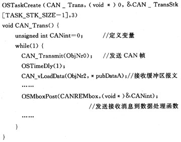
4.2 CAN communication module
The function of the CAN communication module is to realize the information transmission between the vehicle controller and other nodes. Cyclic transmission, transmission period of 20 ms, communication rate of 250 kbps, interrupt call CAN communication service program.
Create CAN communication module task CAN_Trans, task priority 3:
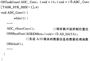
4.3 A/D module
The function of the A/D module is to complete the reading of the battery voltage, the accelerator pedal sensor and the throttle position sensor signal, and perform analog-to-digital conversion, which is called by other functions.
Create A/D conversion module task ADC_Cony, task priority 4:
4.4 vehicle control main program module
After the self-test of each module of the hybrid vehicle system is successful, the vehicle controller requires that the battery be activated to enter the normal EV mode. Then enter the different processing modules by judging the gear position, key switch and accelerator pedal. The control strategy includes the vehicle control strategy and the energy flow management strategy to realize the control output based on the torque algorithm.
Create the vehicle control main program task Drive_Ctr, priority 9:
OSTaskCreate(Drive_Ctr, (void*)&Drive_Ctr[OS_TASK_STK], 9)
This article is limited to the space and no longer introduces other modules, the general process is similar.
Conclusion
With the continuous development of automobile technology and increasingly strict regulations, automotive electronic systems will become more and more complex, and the use of operating systems to manage and coordinate complex tasks will become an inevitable trend.
In this paper, the software and hardware design of the hybrid vehicle controller is used to explain the migration process of μC/OS-II system, and the system software design is optimized to fully meet the system requirements. The vehicle test has achieved good results.
6 Inch Woofer Speaker
6 Woofer Speaker,Sub Woofer Speaker,6 Inch Woofer Speaker,High Power Audio Speaker
Guangzhou Yuehang Audio Technology Co., Ltd , https://www.yhspeakers.com
