Design of Vehicle Light Control System Based on LIN Bus
The rapid development of electronic technology has brought tremendous changes to the development of automobiles, but with the increase of automobile electronic devices, the wiring of the body has been increased and complicated. The traditional centralized body control system design is difficult to meet the sharing and real-time exchange of large amounts of data in different electronic units. Therefore, the system operation reliability is reduced, and the difficulty of fault maintenance is increased. Therefore, it is imperative to improve the humanity and intelligence of the automotive body electronic control system to reduce the wiring harness, reduce costs, and achieve information sharing, so as to improve the reliability and maintainability of the system.
1 LIN bus technology
LIN (Local Interconnect Network) is a low-cost serial communication protocol, which is defined based on the widely used SCI (UART), and the hardware implementation cost is low. It is based on a master-slave structure, a single master node has multiple slave nodes, does not require an arbitration mechanism, uses single-wire communication, reduces the weight and cost of a large amount of wiring harness, and its application goal is a low-speed system with low bandwidth performance requirements, with a communication rate of 1-20 Kb / S, is currently mainly used to replace the CAN bus in the automotive networked electronic control system for real-time communication between low-end electronic control devices.
LIN bus message transmission is formed and controlled by the format of the message frame. The message frame transmits synchronization and identifier information from the master task to the slave task, and transmits the information of one slave task to other slave tasks. The host task is located inside the host node, and it is responsible for the schedule of the message and the header of the sent message (HEADER). The slave task is located in all the nodes (that is, the master and slave), and one of them sends a message response (RESPONSE).
A message frame (see Figure 1) is composed of a header sent by a master node and a response sent by a master or slave node.

The message header of the message frame includes a synchronization interval field (SYNCHBREAK FIELD), a synchronization field (SYNCH FIELD) and an identifier field (IDENTITY FIELD). The message frame response (RESPONSE) consists of 3 to 9 byte fields: 2, 4 or 8 byte data field (DATA FIELD) and 1 byte checksum field (CHECKSUM FIELD). The byte field is separated by the inter-byte space, and the header and response of the message frame are separated by a response space within a frame. The minimum inter-byte space and intra-frame response space are 0.
2 Hardware circuit design of car lamp system
2.1 Introduction to the solution of the car light system
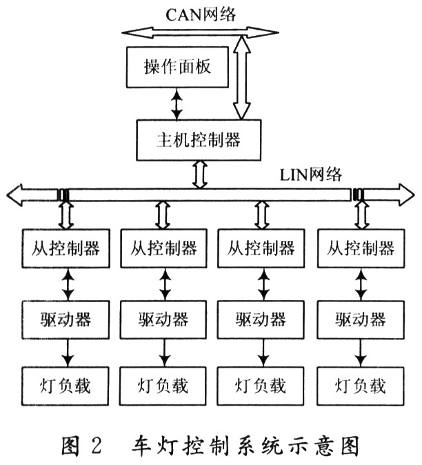
The entire car light system includes five modules (see Figure 2): a host node, responsible for scanning the switch information from the operation panel (such as low beam lights, fog lights, turn signals) and the switch information from the CAN network (such as brake lights) . And send it to the four slave nodes through the LIN bus; the four slave nodes include two control nodes at the front and the rear of the vehicle, which are responsible for receiving the switch information from the LIN bus, controlling the load action of the car lights, and collecting the driving chip The feedback of the lamp failure information is fed back to the host through the LIN bus, and the host node is responsible for the processing and display of the failure information.

2.2 Hardware selection and description
The master and slave MCU select Frescare's MC9S08DZ60 and MC9S08SG04 chips respectively. The DZ60 chip integrates a CAN controller and two SCI modules, which can be used as a CAN / LIN gateway to connect the car light control module and other body networks to realize the unified vehicle network communication. SG04 is an automotive-grade low-cost chip specially developed by FREESCALE for the network control node at the bottom of the car body. It integrates an SCI module, two PWM modules and multiple A / D conversion modules, and can be directly used as a slave node of the LIN network. And can easily realize the control of the load of the lamp and the collection of simulated load fault information.
LIN transceiver selects InfineonTLE6258 series transceiver. TLE6258 is a single-line transceiver, suitable for LIN protocol, with a transmission rate of up to 20 Kb / s, low power consumption, short-circuit protection and over-temperature protection, suitable for automotive and industrial applications. In order to reduce current consumption, TLE6258 provides an idle mode. In idle mode, TLE6258 exits bus activity, and the current is reduced to a minimum, so as to achieve the purpose of reducing power consumption. In the normal operating mode, the idle mode is entered by setting the ENN pin; in the idle mode, by sending a wake-up frame on the bus, the master or slave can be woken up from the idle mode and returned to the normal operating mode. After entering the normal mode, the ENN pin is reset to 0, releasing the RxD pin to transmit data.
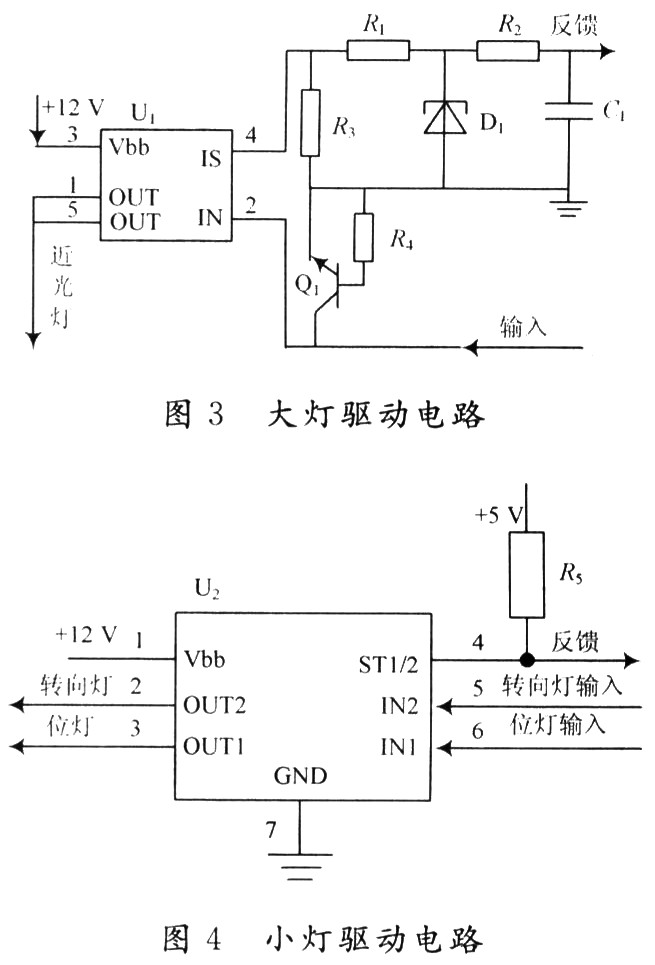
The power drive chip selects Infineon's BTS series drive chip: BTS6143D is used to drive headlights, such as low beam lights, fog lights, BTS724G is used to drive small lights, such as turn signals, position lights. BTS6143D is an N-channel FET power tube, internally integrated charge pump, current drive, and has the fault feedback function of load current detection, including overload, over temperature and short circuit detection, BTS6143D is a single channel input and output, which can realize the analog of the load current Diagnostic feedback; BTS724G is a power MOSFET high-level switch, with four-channel input and output, and each pair of input and output is independent of each other, can output digital diagnostic feedback signal. As shown in Figure 3, Figure 4 shows the design of the driving circuit of the headlight and the design of the driving circuit of the small lamp with the low beam lamp, the turn signal lamp and the position lamp as examples.

3 Software design of the car light system
The software design of the system includes three relatively independent module designs: the master scans the switch information from the operation panel and the CAN bus; the communication module between the master and slave nodes; the slave node's action control of the lamp load And fault information collection module. The design of the last two modules is the core of the software design part of the entire system.
3. 1 LIN communication module design
The LIN communication network contains five nodes: a master node and four slave nodes, where the master node is responsible for sending the switch information to control the turning on and off of the lights to the four slave nodes, and periodically query each slave node and receive each slave node Responding to the fault information; four slave nodes control the load operation of the car's lights in four directions: right front, right rear, left front, and left rear, and collect the fault information of each light synchronously, waiting for the master node to query it. Send to the host. Define five identifiers ID_0 ~ ID_4, which respectively represent the exclusive addresses of the master node and the four slave nodes, which are used to control the accurate transmission of the message to the destination node. When the master asks each slave node for fault information, only the exclusive address The child node consistent with the current message identifier responds to the message and sends the fault information to the host node; define the identifier ID_5 to indicate the common address of all child nodes. When the host sends the light switch information, ensure that all child nodes respond to the current Message, and control the load action of the lamp according to the switch information.
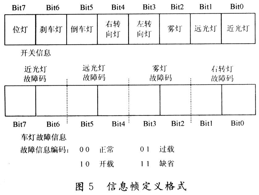
The LIN network host node contains host tasks and is responsible for scheduling message transmissions. There is no arbitration mechanism defined in the LIN communication protocol. Therefore, any slave task that wants to send a message must pass the scheduling of the master task: the master task sends the packet header, and the slave task that matches the identifier sends a response frame. Each node in the LIN network contains slave tasks. The slave task in the master node is responsible for sending the switch information of the lamp to each slave node and receiving the response frame from the slave node; the slave task in the slave node is responsible for sending the fault information detected by the slave to the master The node receives the switch information sent by the host node. The switch information and the fault information each occupy one byte of the data field of the subordinate LIN message frame. Its definition format is shown in Figure 5. The switch information occupies one data byte and contains all the light switch information. The logic "O" indicates the corresponding The light switch in the position is closed, and the logic "1" indicates that the light switch in the corresponding position is open; the light fault information of each slave node occupies a data byte, and the fault information of the right front light is shown in Figure 5 The coding of the fault information is shown in the figure.

3.2 Design of intelligent driving software for vehicle load
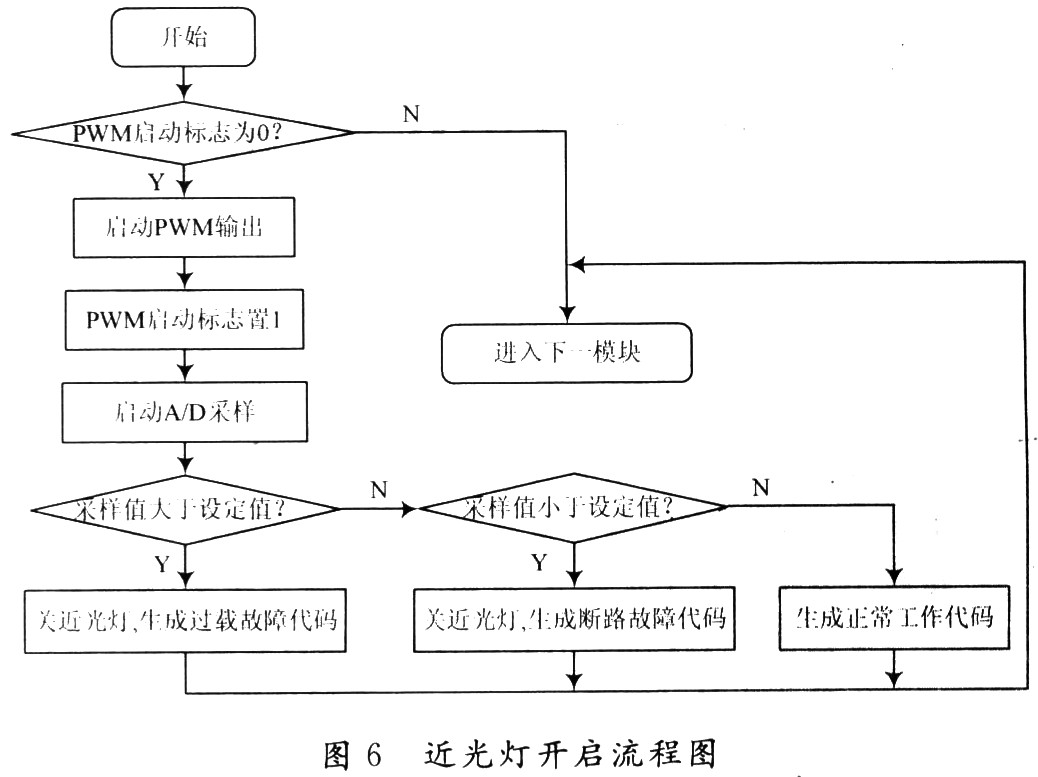
The load failure of the lamp is most likely to occur at the moment of turning on. In order to reduce the instantaneous overshoot of the headlight (low beam) when it is turned on and prolong the service life of the headlight, the PwM control method is used when it is turned on, and the PWM is gradually increased when it is turned on. The duty cycle is up to 100%, so that the voltage of the low-beam light gradually rises to the power supply voltage. The control switch of the low-beam light adopts the BTS6143D chip. Its integrated current feedback function can output a complete according to the actual current through the car. The feedback current is proportional to the peripheral circuit design of the IS pin of the feedback pin in Fig. 3, which converts the current output to O ~ 5V voltage output for the A / D sampling of the slave MCU. When the control switch is turned on according to the command while the system is running, A / D real-time voltage feedback will be started. If the sampled value is lower than the set value, it will be regarded as a broken lamp fault. If the sampled value is greater than the set value, it will be considered as overload or short circuit. If the fault occurs, the slave MCU will quickly turn off the switch to protect the device, and generate corresponding fault information to be fed back to the host node when the host interrogates. The host node decodes the fault information and displays it through the LED. The software design process of the low beam lamp is shown in Figure 6.

3.3 Anti-interference redundancy software design
The operating conditions of the car are extremely bad. The power supply voltage of the generator fluctuates in a large range and the high-frequency electromagnetic interference at the moment of engine ignition is a great interference to the body network system; during the use of the car, due to line insulation Factors such as wear or unreliable connectors may cause disconnection or short circuit of the LIN subnode from the network. According to this, the bus fault is divided into instantaneous interference fault and permanent fault, and the corresponding reliability redundancy design is carried out: the use of automotive-grade high-performance chips on the hardware, and the command and status of the child nodes in the software communication design The information adopts a feedback mechanism: after the master sends the switch information to each slave node, it starts a 500 ms timer. When the time expires, the master queries each sub-node in turn and requests it to feedback its status information. Under this mechanism, once the child node appears in the communication: no feedback command and status; data frame checksum error; the command received by the child node is inconsistent with the command sent by the master node, the master node immediately resends the command, Ensure the correctness of the information received by each child node. If a slave node has no feedback information for a long time, it can be considered that this node has been lost from the network, and the master node generates the corresponding fault information and displays it through the light-emitting diode; if the LIN bus is shorted to ground, the LIN bus has always been displayed Sexual state (low level state), the host can not receive any feedback information from the slave node, the host will turn off the LIN transceiver, protect this device, and display the fault to the driver.
4 Conclusion
A light control system solution based on LIN bus is proposed. Experiments show that the bus-based control system solution has simpler wiring, clear structure, and stronger independence between different control modules than the traditional centralized control solution, which is convenient for future system maintenance and system. The advantages such as upgrade and expansion have certain feasibility.
Panasonic understands manufacturers` challenges in adapting to the demands of increasingly wider market segments. So Panasonic designed a common platform that incorporates jumper wire and radial solutions in both the high-density and high-speed arenas, and an expanded axial solution with built-in jumper wire flexibility.
Radial Insertion Machine,Universal Radial Insertion Machine,Panasonic Radial Insertion Machine,Panasonic Insertion Machine
Shenzhen Keith Electronic Equipment Co., Ltd. , https://www.aismtks.com
