In the security monitoring system, video signal transmission is a crucial part of the whole system. The choice of media and equipment to transmit video signals will directly affect the quality and reliability of the monitoring system. At present, the mediums used to transmit video signals in the monitoring system mainly include coaxial cables, twisted pairs, and optical fibers, and the corresponding transmission devices are coaxial video amplifiers, twisted pair video transmission devices, and optical transceivers.
This article refers to the address: http://
Coaxial cable is used earlier and is the longest used transmission method. Later, due to the need for long-range and large-scale image monitoring and the increasing demand for surveillance image quality, a large number of optical fibers were used in surveillance networks to transmit video signals. As for the twisted pair cable used in the video surveillance network, it is a recent matter. Its emergence mainly solves two problems: on the one hand, it solves the high-quality video signal transmission in the range of 200 meters to 2000 meters. The problem is that the coaxial cable transmission is difficult to meet the requirements within this distance and the optical transmission is uneconomical; on the other hand, it solves the wiring problem of the large-scale intensive monitoring network, the size and flexibility of the twisted pair itself. Overcome a lot of wiring problems when using coaxial cables. Of course, the twisted pair cable also has the advantages of strong anti-interference ability and low price. It is precisely because the twisted pair cable solves these problems that have long plagued people, so its application in the monitoring network immediately attracted widespread attention in the industry, and has been widely used in engineering practice in a short period of time, and Has achieved good application results.
Typical application of video signal twisted pair transmission
Figure 1 shows a block diagram of a typical application for twisted pair transmission.
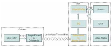
Figure 1 Typical application block diagram of video signal twisted pair transmission
On the camera side, a passive transformer is generally used to convert the single-ended CVBS video signal into a differential video signal; the twisted pair transmission device completes the conversion of the differential signal to the single-ended signal and the amplification, filtering and driving of the video signal; the signal output can be connected to Monitor, DVR device or video matrix device. Twisted pair cables are generally Category 5 twisted pair cables, such as network cables.
Traditional solution for twisted pair transmission of video signals
Traditional solutions typically use passive emissions (such as baluns) and active reception (such as the EL5175). In the active receiving circuit, it is necessary to design a balanced network composed of RC. The DIP switch is used to set the compensation parameters under different compensation distances. At the same time, two mechanical potentiometers are generally needed for fine adjustment of brightness and chromaticity.
Because the traditional scheme adopts the manual equalization method, and the factors such as the quality of the network cable, the installation distance and the parameter dispersion of the container parts in actual application, the compensation effect of the compensation parameters set by the dial switch is not very satisfactory. Although the compensation quality can be improved by fine-tuning the two mechanical potentiometers, since the adjustment of the two potentiometers is mutually influential, the field engineers are not well aware of the scale of the adjustment.
Video signal twisted pair transmission scheme
Maxim's 1200-meter adaptive video signal transmission scheme is: MAX4445+MAX7474+MAX11504, which adopts three-stage structure: the first stage uses MAX4445 with external RC network to realize the conversion and pre-equalization of differential signals to single-ended signals; The second stage adopts MAX7474 to realize automatic signal equalization, which compensates for the difference caused by the quality of the network cable, the installation distance, and the dispersion of the parameters of the container. The third stage uses MAX11054 to achieve signal filtering, buffering and ESD protection. The principle circuit is shown in Figure 2. 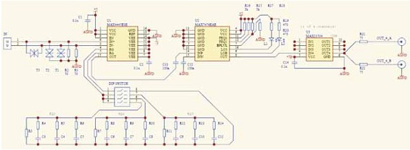
Figure 2 1200 m adaptive video signal transmission scheme
The advantages of this program are:
· Eliminate the difference in compensation effect caused by the difference in wire quality
Due to the actual security engineering, there are many types of network cables used by users, and the quality will be different. The compensation parameters set in the transmission equipment are debugged under the network cable of a specific material. Therefore, when another network cable is laid in the project, the compensation effect will be different. In the Maxim solution, the MAX7474 chip with automatic equalization is used, which can eliminate the difference in compensation effect caused by the difference in wire quality.
· Eliminate the difference in compensation effect caused by the difference in actual installation distance in the project
The compensation parameters set in the transmission equipment are generally debugged at a certain distance, such as 600 meters. In the actual security project, the installation distance will not be exactly 600 meters, which may be 650 meters. The compensation effect of the compensation parameters set by the DIP switch in the device will be different. In Figure 2, the automatic equalization function is adopted. The chip MAX7474, which can well eliminate the difference in compensation effect caused by the difference in the actual installation distance in the project.
· Eliminate the difference in compensation effect caused by the difference in the parameters of the resistive container in the equalization network
As is known, the accuracy of commonly used resistors and capacitors is low, the accuracy of the resistor is generally 1% or 5%, and the accuracy of the capacitor is generally 10% or even 20%. Therefore, even if the compensation parameters of the equalization network are debugged under the specific installation distance and the network cable of the specific material, the compensation effects of the two types of the resistive container parts will be different due to the dispersion of the parameters. The circuit of Fig. 2 adopts the chip with automatic equalization function, which can well eliminate the difference of the compensation effect caused by the difference of the parameters of the resistive container in the equalization network.
Comparing Figure 3, Figure 4 and Figure 5, we can clearly see the compensation effect of the scheme on the video signal.
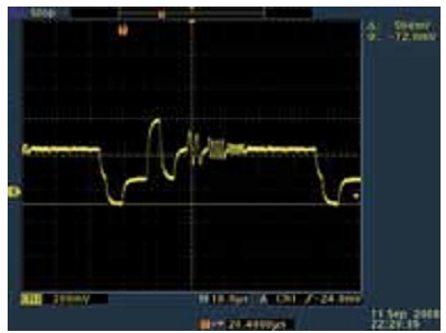
Figure 3 800 m transmission distance (without any compensation) 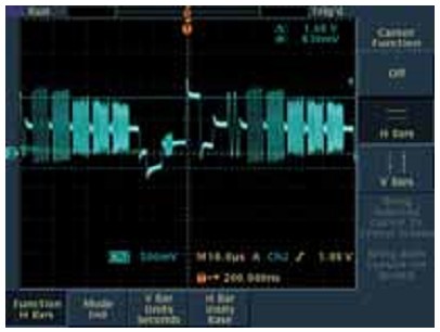
Figure 4 800 m transmission distance (first stage MAX4445 compensation)
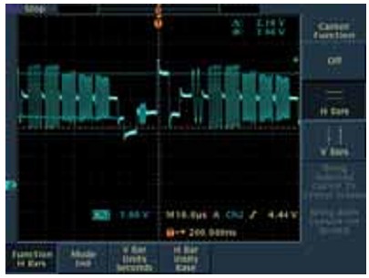
Figure 5 1200 m transmission distance (the first stage MAX4445 and the second stage MAX7474 jointly compensate)
Conclusion
The MAX7474 provides cable loss compensation when a composite video signal is transmitted over an unshielded twisted pair. It adaptively equalizes the cable length by monitoring the sync signal of the color video signal at the output and the amplitude adjustment gain of the burst signal. When using cable transmission, the MAX7474 fully equalizes the loss of the 300m transmission cable and effectively improves the signal integrity of the 600m transmission cable. The MAX7474 accepts NTSC and PAL differential video signals, including a unity-gain video output driver and an adjustable back-shoulder clamp DC level. The device also provides LOS and LOB logic output indication.
In this scheme, we use the MAX4445 with an external RC network to compensate for the specific transmission distance, and combine the characteristics of the MAX7474 automatic equalization to compensate for the difference between the quality of the network cable, the installation distance and the dispersion of the parameters of the RC. The adaptive transmission of the 1200-meter video signal is solved.
Wire To Board Connector
Wire To Board Connector
ATKCONN ELECTRONICS CO., LTD , https://www.atkconn.com
