|
Simple small radio experiment I once got a six-lamp radio at my friend's house, and after disassembling the machine, I assembled a small radio station with 6Pl power amplifier tubes.
The circuit is shown in the figure below: B1, B2, G, R1, R2, C2, C3, C4 and C5 are all disassembled products. Because the volume of the power supply filter capacitor in the machine is too large, a color TV filter capacitor is used. L1 selects 22mm enameled wire to wrap 100 turns on the magnetic ring of MX-2000. L2 determines the radio frequency of the station. If the frequency is selected in the middle wave band, L2 can use 35mm enameled wire on the medium wave magnet bar for 30 + 50 turns, or use 13mm enameled wire tightly wound 90 turns on the 25mm paper tube. In this way, the transmission frequency will fall between 550-1650kHz. If the short wave band is selected, L2 can be wound 9 turns between the 16mm paper tube with 0.5mm enameled wire. The frequency of the oscillator thus constructed falls between 6 and 18 MHz. C5 is an air duplex, and its capacity is 360pFx2. B1 is the original power transformer. For high voltage part rectification, 4 IN4007 are used. B2 is the original output transformer. C2, C3, mica capacitors disassembled inside the machine, C2, C3 withstand voltage is better than 400V. R1, R2 can also buy cement resistance. Because the scattered power is large, its power should be ≥IW. TX is a 1/4 antenna, which can be replaced by a thick wire, the length is about 1/4 of the emission wavelength. The author chose 3mm and 8m long enameled wire. The whole circuit installation does not need to use copper-clad board, directly use a piece of glue board, drill on it. Hole, can be welded by scaffolding. As long as the components are good, the circuit will start to oscillate after installation. When oscillating, a light blue electron flow can be seen in the G, accompanied by a "sizzle" sound. If there are conditions, a simple field strength meter can be made to adjust the R2 to maximize the transmitted field strength. The antenna can be mounted vertically on the wall via insulators. After connecting the antenna, input an audio signal of about 5W at B2 to extend the distance between a radio and the transmitter. The radio should receive the signal clearly and the distortion should not be obvious. If the hum is too loud when launching,
Grounding can solve it. After actual measurement, the transmission power is as large as 4.5W, so the relevant regulations of the National Non-Committee must be followed during the experiment. ![]()
|
In-depth analysis of the first-level cache and second-level cache of the technical zone CPU eMMC mass burning dilemma, do you really know? Isolation flyback and non-isolated BUCK application design plan Schottky barrier diode selection and application guide How to use Altium in program design Designer puzzle?

Follow WeChat
Interesting and informative information and technical dry goods

Download Audiophile APP
Create your own personal electronic circle

Follow the audiophile class
Lock the latest course activities and technical live broadcast
related suggestion
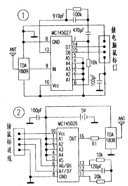
Design and manufacture of remote control device for computer mouse port (including circuit diagram)
Design and manufacture of remote control device for computer mouse port (including circuit diagram) The device and the coded circuit MC145026 / MC145027 ...
Published on 2006-04-17 19:13 • 511 views

[Photo] Simple low-pass filter circuit
Published on 2006-04-17 19:12 • 253 times read
![[Photo] Simple low-pass filter circuit](http://i.bosscdn.com/blog/20/06/41/7191221419.gif)
[Photo] Simple and practical inverter power supply
This is an excellent performance
Posted at 2006-04-16 23:05 • 335 views
![[Photo] Simple and practical inverter power supply](http://i.bosscdn.com/blog/20/06/41/623541253.gif)
[Photo] Simple and practical 3-key interlocking electronic switch
Posted at 2006-04-16 17:59 • 581 times read
![[Photo] Simple and practical 3-key interlocking electronic switch](http://i.bosscdn.com/blog/20/06/41/6175947634.gif)
[Photo] Simple temperature controller circuit
Posted at 2006-04-16 17:24 • 254 views
![[Photo] Simple temperature controller circuit](http://i.bosscdn.com/blog/20/06/41/6172411284.gif)
[Photo] Simple and practical thermostat controller circuit
Posted at 2006-04-16 17:15 • 197 times read
![[Photo] Simple and practical thermostat controller circuit](http://i.bosscdn.com/blog/20/06/41/6171539767.gif)
[Photo] Simple and practical remote control switch circuit
Posted at 2006-04-16 17:15 • 407 views
![[Photo] Simple and practical remote control switch circuit](http://i.bosscdn.com/blog/20/06/41/6171524607.gif)
[Photo] Simple and practical remote control switch
2003, Issue 7, Category: Electronic Production & nb ...
Posted at 2006-04-16 17:14 • 261 times read
![[Photo] Simple and practical remote control switch]()
[Photo] Simple, special voltage regulator circuit
Published on 2006-04-15 23:23 • 273 times read
![[Photo] Simple, special voltage regulator circuit](http://i.bosscdn.com/blog/20/06/41/5232339884.gif)
[Photo] Simple single key switch circuit
If the SW lead is more
Posted at 2006-04-15 23:23 • 1173 views
![[Photo] Simple single key switch circuit](http://i.bosscdn.com/blog/20/06/41/5232322827.jpg)
[Photo] Simple white noise signal generator
& n ...
Published on 2006-04-15 23:03 • 1191 times read
![[Photo] Simple white noise signal generator]()
[Photo] Simple circuit diagram of the field strength meter
Published on 2006-04-15 20:50 • 766 views
![[Photo] Simple circuit diagram of the field strength meter]()
[Photo] Simple fool power amplifier
"Simple" means the circuit of the amplifier is simple, making it easier, as long as the picture ...
Posted at 2006-04-15 13:04 • 2479 views
![[Photo] Simple fool power amplifier](http://i.bosscdn.com/blog/20/06/41/513432946.jpg)


![[Photo] Simple low-pass filter circuit](http://i.bosscdn.com/blog/20/06/41/7191221419.gif)
![[Photo] Simple and practical inverter power supply](http://i.bosscdn.com/blog/20/06/41/623541253.gif)
![[Photo] Simple and practical 3-key interlocking electronic switch](http://i.bosscdn.com/blog/20/06/41/6175947634.gif)
![[Photo] Simple temperature controller circuit](http://i.bosscdn.com/blog/20/06/41/6172411284.gif)
![[Photo] Simple and practical thermostat controller circuit](http://i.bosscdn.com/blog/20/06/41/6171539767.gif)
![[Photo] Simple and practical remote control switch circuit](http://i.bosscdn.com/blog/20/06/41/6171524607.gif)
![[Photo] Simple, special voltage regulator circuit](http://i.bosscdn.com/blog/20/06/41/5232339884.gif)
![[Photo] Simple single key switch circuit](http://i.bosscdn.com/blog/20/06/41/5232322827.jpg)
![[Photo] Simple fool power amplifier](http://i.bosscdn.com/blog/20/06/41/513432946.jpg)
