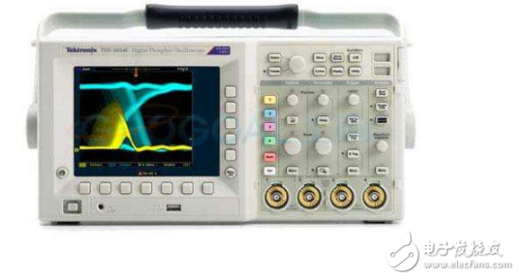
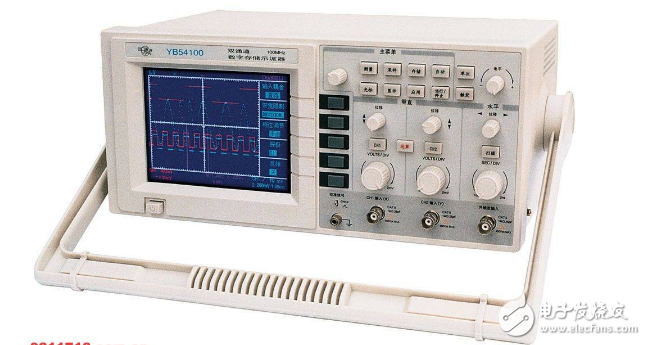
An oscilloscope is an electronic instrument that can directly display a voltage change waveform. It can not only observe the change process of an electric signal, but also measure the waveform, such as the amplitude, period, frequency and phase of the voltage. Oscilloscopes are widely used in the production and research of electrical products, and are the "universal instruments" for the maintenance of household electronic products. The commonly used oscilloscopes can be divided into single trace oscilloscopes, dual trace oscilloscopes, and multi-track oscilloscopes according to the number of display signals. The most widely used oscilloscopes in real work are dual trace oscilloscopes. Because the structure and working principle of the oscilloscope are complicated, there are many knobs that need to be adjusted on the panel during use, so the measurement method of the oscilloscope is very complicated, and it is difficult for the general personnel to grasp. Here, the YB4328 dual-track oscilloscope widely used by power companies is taken as an example to introduce its structure and working principle, and the use process of a good operation method is discussed in detail.
1, the structure of the oscilloscopeThe structure of the oscilloscope includes the oscilloscope tube of the core component of the machine and the adjustment circuit of the oscilloscope tube. The connection circuit outside the machine has a power plug and a signal input probe. The oscilloscope is the core of the oscilloscope. It is a small picture tube consisting of an electron gun, a deflection circuit and a fluorescent screen.

The electron gun is equivalent to a machine gun that emits an electronic "bullet". It consists of a filament, a cathode, a control grid, a first anode, a second anode, and a third anode. The control grid and the anode are formed in a cylindrical shape and are in the same On the axis. During operation, the filament is energized to heat the cathode, and the cathode is heated to generate electrons. The negatively charged "bullet" of electrons is emitted at a high speed to form a beam of electrons under the acceleration of the three anodes. At this time, there are two regulating components, one is a control gate, and its potential is lower than that of the cathode. By adjusting the level of the potential, the density of electrons emitted by the cathode can be controlled, and the density of the electron flow is related to the brightness of the waveform displayed on the screen. Therefore, the brightness of the waveform can be adjusted by changing the control gate voltage. On the panel, the brightness knob is used to adjust the brightness. The other is three accelerating anodes. The potential of the anode is higher than that of the cathode. Therefore, the electron flow accelerates under the action of the electric field force. The faster the speed, the clearer the waveform of the electron beam on the phosphor screen, so the potential of the anode can be adjusted. To adjust the clarity of the waveform display, the focus knob on the panel is the knob that adjusts the anode potential.

The function of the deflection circuit is to cause the electron beams to be regularly shifted, and a corresponding signal waveform is formed on the phosphor screen. It is two pairs of mutually perpendicular deflection plates mounted to the third anode, a pair of plates placed on the lower plate, called the vertical deflection plate or the Y-axis deflection plate, and the other pair of plates horizontally placed, called the horizontal deflection plate Or X deflection plate.
1.3, the structure of the screenIt is made by applying phosphor on the inner wall of the glass tube. The high-speed electron flow emitted by the electron gun is emitted onto the phosphor of the phosphor screen to generate visible light, and the greater the energy of the electron flow, the higher the brightness of the light spot. The electron flow stop shooting fluorescence can still be retained for a period of time, and people use the afterglow phenomenon of this light to display the trajectory of the electron.
2, the principle of waveform display(1) Add a sinusoidal voltage only to the Y deflection plate, and the spot can make a vertical bright line on the screen.
(2) Sawtooth voltage is applied only to the X deflection plate, and the spot can be printed with a horizontal bright line on the screen.
(3) Synthesis of waves. The sinusoidal voltage of the signal to be measured is applied to the Y deflection plate, and the sawtooth scanning voltage is applied to the X deflection plate, and the frequencies of the two signals of the Y deflection electrode and the X deflection plate are equal or integral. Just like drawing on coordinate paper, a complete signal waveform can be displayed. This is called synchronization of the oscilloscope. Because the waveform is a two-dimensional figure, the electron beam needs to be synchronously applied on the Y-axis and the X-axis to display it completely.
3, oscilloscope panel knobs and function introductionThe knobs, buttons, and sockets on the oscilloscope panel are divided into three parts, including a main unit, a vertical channel, and a horizontal channel.

In the left area of ​​the panel, the knobs and buttons arranged from top to bottom have a brightness knob, a focus knob, a track rotation, a power switch, and a standard signal source. The Brightness knob adjusts the brightness of the waveform. The focus knob adjusts the clarity of the displayed waveform. The track rotation adjustment waveform is symmetrical with the horizontal axis. If the asymmetry can be fine-tuned with a screwdriver, it is generally not necessary to adjust. The power switch adopts a push button type, which is closed when pressed, and is disconnected when it is ejected. The standard signal source is a rectangular wave test signal built into the oscilloscope. The Up-p voltage is 0.5V and a square wave signal with a frequency of 1kHz. Before the oscilloscope inputs the measurement signal, its standard signal should be taken for verification. Measurement signals can be connected for measurement.
High efficient charging speed for Acer laptop, stable current outlet can offer power for the laptop at the same time charge the laptop battery. The best choice for your replacement adapter. The DC connector is 5.5*1.7mm or 3.3*1.0mm. We can meet your specific requirement of the products, like label design. The plug type is US/UK/AU/EU. The material of this product is PC+ABS. All condition of our product is 100% brand new.
Our products built with input/output overvoltage protection, input/output overcurrent protection, over temperature protection, over power protection and short circuit protection. You can send more details of this product, so that we can offer best service to you!
Laptop Adapter For Acer,Charger For Acer,Acer Laptop Adapter ,Ac Adapter For Acer
Shenzhen Waweis Technology Co., Ltd. , https://www.szwaweischarger.com
