The main parameters for measuring solar panels and batteries are:
• Open circuit voltage (Voc), battery voltage when there is no current
• Short-circuit current (Isc), current flowing from the battery when the load resistance is zero
• Battery maximum power output (Pmax), the voltage and current point at which the battery produces maximum power. Usually put IV
Pmax point on the curve as the maximum power point (MPP)
• Pmax voltage (Vmax), battery voltage level at Pmax
• Pmax current (Imax), battery current level at Pmax
• Conversion efficiency (η) of the device, conversion (from absorbing light to electrical energy) and collection when the solar cell is connected to the circuit
The percentage of power.
Second, the composition of the tester system
1.PIC32 module

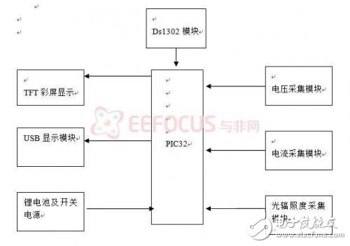
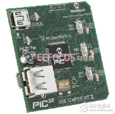
This module uses the PIC32 USB Starter Kit II, which is mainly the bearer center of the program. Its main work is to initialize the module, collect, analyze, calculate, store and other functions.
2. Acquisition module
Current collection
The solar panel receives light, generates current, generates a small voltage through the R9 resistor, and the voltage across the R9 resistor is amplified by the op amp to 50 times, and then the voltage is passed through the voltage follower to the input port of the AD end of the PIC32 board. After the AD conversion, the voltage is converted into a digital signal, and then processed by the PIC32, and converted into an actual voltage value and sent to the display system. The schematic diagram of the detection system is shown in Figure 2.1 below.
Voltage collection
The voltage is divided across four 1M ohm resistors to collect the voltage across the R4 resistor. The voltage signal is transmitted to the input port of the AD terminal through the voltage follower, and the voltage is converted into a digital signal by AD conversion, and then processed by the PIC32, and converted into an actual voltage value and sent to the display system. The schematic diagram of the detection system is shown in Figure 2.1 below.
Voltammetric characteristics of the battery
By adjusting the size of the R5 digital potentiometer, the continuously changing analog voltage and current signals are continuously transmitted to the PIC32AD terminal input port, and the voltage is converted into a digital signal by AD conversion, which is converted into actual voltage value and current value through software design. The power value is sent to the display system (TFT color screen) to draw current and voltage curves, and multiple sets of data are collected to determine the performance of the solar cell.
Coaxial Power D-Sub Solder Cup
Coaxial Power D-Sub Solder Cup Contacts with Mixed or Full Layout
Transmit Radio Frequency Signals
The Coaxial D-Sub have like the Power D-Subr replaced the two rows in a Standard Density connector with a coaxial contact that take up about the same size as the two rows of signal contacts. The Coaxial D-Sub is exactly the same size as the Standard Density connector but instead of example 9 positions of signal pins it has 2 power contacts , or instead of 37 positions of signals it has 8 coaxial contacts.
The Impedance for the coaxial contacts are 50Ω or 75Ω
The Coaxial D-Sub with Mixed Layout mixes both coaxial contacts and signal contacts in the same connector. For example the same size as a 15 position Standard Density D-Sub you can have what we call a 7W2, which means there is 7 contacts where 2 of them are coaxial contacts, which means there are 5 signal contacts, so 5 signals and 2 coaxial. See the Layout in the Tech Specs on the bottom, there are a lot of combinations of the Mixed Layout alternative.
Antenk's Coaxial D-Sub connectors are available in 5 standard shell sizes with 23 multiple contact arrangements. These reliable, robust combination d-sub connectors allow a combination of signal and coaxial contacts in cable mount, vertical board mount & right angle board mount termination type variations.
Features
Coaxial d-sub for a variety of applications in cable mount.
Signal contacts come pre-loaded. Coaxial contacts supplied - Not Pre-Loaded.
Available in 5 standard shell sizes with 23 multiple contact arrangements: 1W1/ 2V2 /2W2 /3V3/ 3W3/ 5W1/ 5W5
/ 7W2/ 8W8/ 9W4/ 11W1/ 13W3/ 13W6 /17W2/ 17W5 /21W1/ 21W4/ 24W7/ 25W3 /27W2/ 36W4/ 43W2/ 47W1
Allows combination of signal and coaxial d-sub contacts.Materials
Shell: Steel, nickel plated
Insulator: PBT + 30% fiber-glass - Black, U.L. rated 94V-O
Contacts: Brass - Gold flash over nickel
Notes
Panel Cut-Outs
5W1 = Standard 9 Pin Shell
3W3 / 3W3K / 7W2 / 11W1 = Standard 15 Pin Shell
5W5 / 9W4 / 13W3 / 17W2 / 21W1= Standard 25 Pin Shell
8W8 / 21WA4 = Standard 37 Pin Shell
Other Contact Arrangements Available Upon Request.
Coaxial D-Sub Connector, Coaxial D-Sub with Mixed Layout, Coaxial D-Sub with Mixed with Full Layout,Coaxial D-Sub Male, Coaxial D-Sub Female
ShenZhen Antenk Electronics Co,Ltd , https://www.antenksocket.com
