Matrix-based keyboards are often used as input devices in microcontroller-based (MCU) projects. The general practice of connecting a matrix keyboard to a microcontroller requires the use of multiple I/O pins of the microcontroller. The MCU then uses a scanning algorithm to confirm which keys are held down. One drawback of this approach is the need for a large number of MCU I/O pins to connect to the keyboard. For example, connecting a 4 x 3 keyboard requires 7 digital I/O pins. A problem arises when the project uses a low pin count MCU, or if the MCU used does not have enough I/O pin counts available.
There are two solutions to this problem: use an off-the-shelf I/O expander, or use a resistor bank to set a unique voltage for each key, then use the analog pin to read the voltage value and determine Which key is held down. Each program has its shortcomings.
Since in most cases, the I/O expander needs to read and write data through a special communication protocol (such as I2C protocol or SPI protocol), the MCU needs to have a built-in communication module, or the user needs to implement the relevant communication protocol software, and this Significantly increased the burden of the MCU. On the other hand, when the number of buttons is increased, it is cumbersome to assign a unique voltage to each button through the resistor, which will eventually result in a smaller voltage margin. In addition, since the resistance value varies with temperature, using a small voltage margin may cause a reading error, and even a switch bounce may become an important cause of voltage error. Another drawback of this approach is that it requires an analog input pin in the MCU. The example described here shows a solution that solves all of the above problems efficiently, and has several advantages: it requires only two I/O pins, regardless of the number of switches connected; no special communication protocol is required; No analog pins are required. This example is based on two CD4017 Johnson counters, which are common and inexpensive.
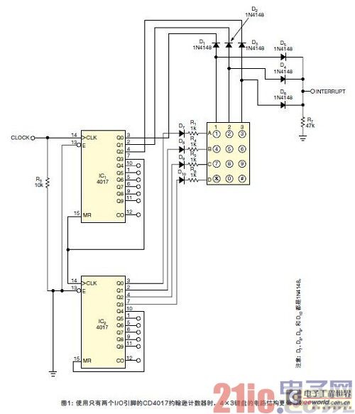
Figure 1 shows the circuit used in a 4 x 3 keyboard. R1, R4, R5 and R6 are used for current limiting, and D7, D4, D5 and D6 form an "or" gate.

The example described here shows how to use this method to read a 4x3 keyboard. One CD4017 is used to control the keyboard row and the other controls the keyboard column.
The MCU generates a clock signal and then supplies it to the counter IC of the control column. Initially, the 0th output of the column counter and the row counter is at a logic high. The column counter will increase after the clock pulse is received. When the fourth clock pulse is received, the column counter is reset and the row counter is incremented by one at the same time. After the column controller is reset, the row controller is incremented and reset after receiving the fifth clock pulse from the column controller. While generating the clock pulse, increase the count variable of the MCU and reset the count variable to 1 when the fifth clock pulse reaches the row controller. The two outputs of the keyboard are ORed and connected to an external interrupt pin of the MCU.
Interrupts occur only when a button is pressed when the relevant buttons for the row and column are at logic high. If the row or column of the button is at a logical zero value, no break will occur.
When an interrupt occurs, the MCU reads the count value at that time, and the value read corresponds to the button just pressed.
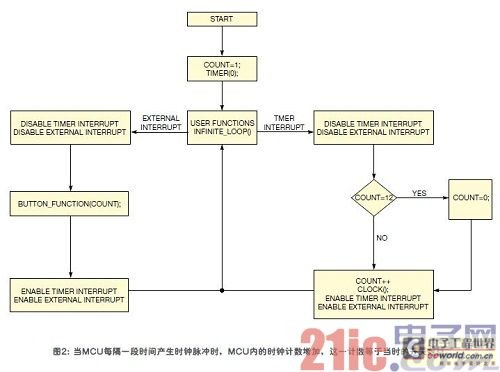
When the MCU generates a clock pulse every once in a while, the clock count in the MCU increases; this count is equal to the number of switches on the keyboard, and pressing these switches can cause an interrupt. The flow chart in Figure 2 describes this situation.

Note: Although this example only shows the 4 x 3 keyboard reading method, the remaining output of the two 4017 counters can be used to read the 10 x 10 keyboard. In addition, if necessary, you can cascade more 4017IC to expand the keyboard.
Commutators For Industrial Motors
Commutators For Industrial Motors,Commutator For Fan Motors,Commutator For Switching Motors,Commutator For Auto
ZHEJIANG JIAGU ELECTRIC APPLIANCES CO. LTD , https://www.chinajiagu.com
